Mattress edge protection spring and mattress
A technology for edge protection and mattresses, which is applied in the field of spring mattresses, and can solve problems such as affecting the appearance and bulging of mattresses
- Summary
- Abstract
- Description
- Claims
- Application Information
AI Technical Summary
Problems solved by technology
Method used
Image

Examples
Embodiment Construction
[0016] The invention will be described in further detail below in conjunction with specific embodiments.
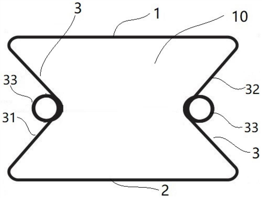
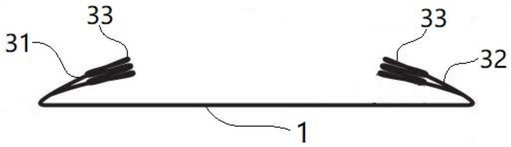
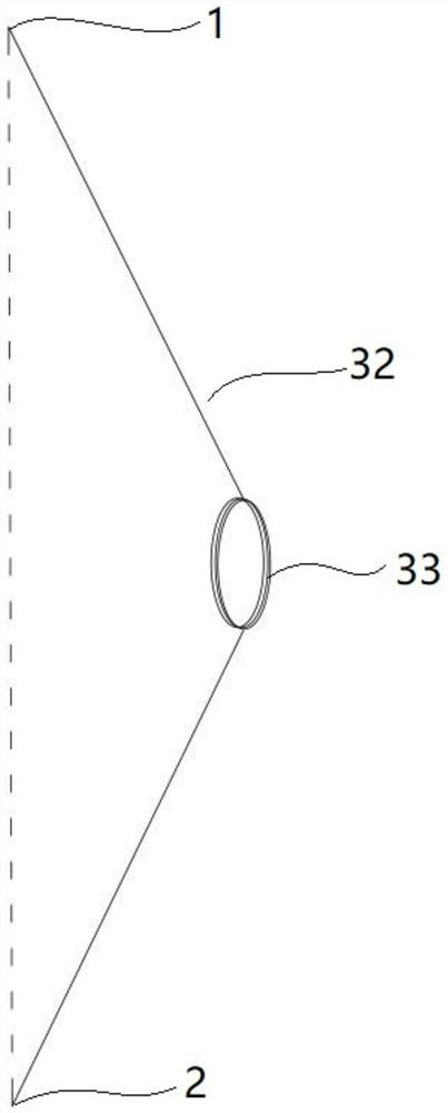
[0017] Such as Figure 4 The shown mattress comprises spring bed 20, and a plurality of such as figure 1 The edge protection spring 10 shown. The edge protection spring 10 is integrally wound by a steel wire. The top edge 1 and the bottom edge 2 of the edge protection spring 10 are respectively fixed on the spring layer 20 (see Figure 4 ) top and bottom of the sidewall. Such as figure 1 As shown, an elastic connecting portion 3 is connected between the top edge 1 and the bottom edge 2 of the edge protection spring 10 , and the elastic connecting portion 3 includes a left elastic connecting portion 31 and a right elastic connecting portion 32 . The left elastic connecting part 31 connects the left end of the top side 1 and the left end of the bottom side 2, and the middle part of the left elastic connecting part 31 is arched to the right. The right elastic connectin...
PUM
 Abstract
Description
Claims
Application Information
 - R&D
- Intellectual Property
- Life Sciences
- Materials
- Tech Scout
- Unparalleled Data Quality
- Higher Quality Content
- 60% Fewer Hallucinations
Browse by: Latest US Patents, China's latest patents, Technical Efficacy Thesaurus, Application Domain, Technology Topic, Popular Technical Reports.
© 2025 PatSnap. All rights reserved.Legal|Privacy policy|Modern Slavery Act Transparency Statement|Sitemap|About US| Contact US: help@patsnap.com