Piezoelectric viscous damper

A technology of viscous damper and piezoelectric driver, which is applied in the direction of building components, earthquake resistance, building types, etc., to achieve the effect of reducing cost and volume and avoiding time lag problems

Pending Publication Date: 2021-12-07
NANHUA UNIV
View PDF7 Cites 0 Cited by
  • Summary
  • Abstract
  • Description
  • Claims
  • Application Information

AI Technical Summary

Problems solved by technology

[0008] Aiming at the deficiencies of the prior art, the present invention provides a piezoelectric viscous damper to solve the problems of time lag and precision caused by adding a displacement amplification device to amplify the output displacement of the traditional piezoelectric viscous damper

Method used


Image

  • Piezoelectric viscous damper
  • Piezoelectric viscous damper
  • Piezoelectric viscous damper

Examples


Embodiment Construction

[0033] The technical solutions in the present invention are clearly and completely described below in combination with the accompanying drawings in the embodiments of the present invention. Obviously, the described embodiments are only some of the embodiments of the present invention, not all of them. Based on the embodiments of the present invention, all other embodiments obtained by persons of ordinary skill in the art without creative efforts fall within the protection scope of the present invention.

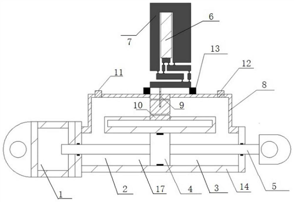
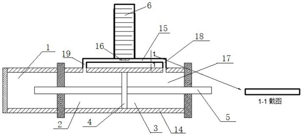
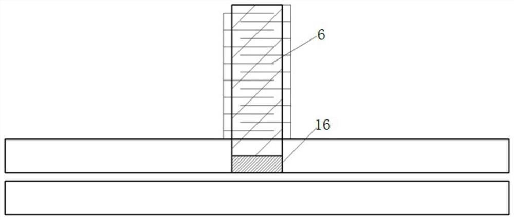
[0034] Such as figure 2 and 3 As shown, a piezoelectric viscous damper provided by the present invention includes a cylinder composed of a main cylinder 17 and an auxiliary cylinder 1, a piston 4, a piston rod 5, a bypass pipeline, a piezoelectric driver 6, The control system and the control board 16 connected to the displacement output end of the piezoelectric driver 6; the main cylinder 17 is filled with viscous fluid, the piston rod 5 is inserted into the main cylinder 1...


PUM


Abstract

The invention discloses a piezoelectric viscous damper. A bypass pipeline is changed into a flat pipe from a universal round pipe, the flat pipe plays a role of a damping hole in a round pipe damper, and the piezoelectric viscous damper is a damper related to the movement speed of a piston and is a semi-active damper with the fastest response speed in the world at present. A control system can control a piezoelectric actuator to generate mechanical strain so as to output displacement, and the required output displacement can be achieved without installing an amplifier device. The height of the flat pipe can be adjusted by adjusting the movement of a control panel according to the real-time acting force, so that the flow rate of viscous fluid is controlled by adjusting the size of the damping hole, and the impact energy of the force on a building structure is absorbed and consumed to the maximum extent; and according to the damper, the purpose of adjusting the damping hole can be achieved without adopting a displacement amplifying device, the problems of time lag and precision caused by the displacement amplifying device are avoided, and the cost and size of the damper are reduced.

Description

technical field [0001] The invention belongs to the technical field of civil engineering vibration control, in particular to a piezoelectric viscous damper, which is a semi-active control system with the fastest theoretical response speed in the world at present. Background technique [0002] As the vibration control of structural engineering has attracted more and more attention, many civil engineering structures (such as buildings, bridges, and nuclear power plants and other industrial production rooms) have increasingly stringent requirements on the vibration environment, and vibration isolation or damping must be carried out for these civil engineering structures. vibration processing. [0003] Vibration control of civil engineering structure is to install some kind of control device structure or mechanism in a specific part of civil engineering structure to scientifically and reasonably control its engineering structure, reduce its impact on acceleration and displacemen...

Claims


Application Information

Patent Timeline
Patent Type & Authority Applications(China)
IPC IPC(8): E04B1/98E04H9/02
CPCE04B1/98E04H9/021
Inventor 戴纳新李聪张明辉谭平周福霖
Owner NANHUA UNIV
Why Eureka
Try Eureka