Screwing mechanism and coupling centering and screwing device

A driving device and pre-tightening technology, which is applied in the direction of drilling equipment, earthwork drilling, drill pipe, etc., can solve the problems that affect the connection performance and sealing performance of the coupling and the casing, the screw teeth are easy to be screwed, and the screwing accuracy is poor. , to achieve the effect of compact overall structure, convenient maintenance and replacement, and simple structural design

Pending Publication Date: 2021-12-07
盐城保源自动化设备有限公司
View PDF1 Cites 2 Cited by
  • Summary
  • Abstract
  • Description
  • Claims
  • Application Information

AI Technical Summary

Problems solved by technology

[0004] The existing coupling tightening device, such as the application number: 201220562170.5, is named: a Chinese patent for a coupling tightening device. There are main tongs and back tongs, the main tongs are respectively connected with a control device and a motor, the back tongs are connected to each other with a pressure sensor and a torque meter, and the back tongs are connected to the cylinder, the torque It can be seen that in the prior art, when the main tong is clamping the coupling, it is easy to clamp more tightly on one side eccentrically, and there is a gap on the other side, and the clamping effect is poor. It is prone to warping and poor screwing accuracy, and what's more, the screw teeth are easy to be screwed, which affects the connection performance and sealing performance between the coupling and the casing.

Method used


Image

  • Screwing mechanism and coupling centering and screwing device
  • Screwing mechanism and coupling centering and screwing device
  • Screwing mechanism and coupling centering and screwing device

Examples


Embodiment Construction

[0054] The following will clearly and completely describe the technical solutions in the embodiments of the present invention with reference to the accompanying drawings in the embodiments of the present invention. Obviously, the described embodiments are only some, not all, embodiments of the present invention. Based on the embodiments of the present invention, all other embodiments obtained by persons of ordinary skill in the art without making creative efforts belong to the protection scope of the present invention.

[0055] It should be noted that in the description of the present invention, terms such as "first" and "second" are only used to describe the purpose and distinguish similar objects, there is no sequence between the two, and they cannot be interpreted as indicating or imply relative importance. In addition, in the description of the present invention, unless otherwise specified, "plurality" means two or more.

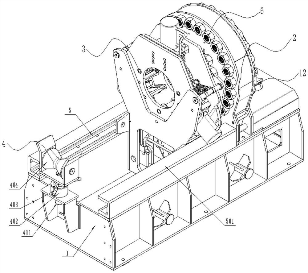
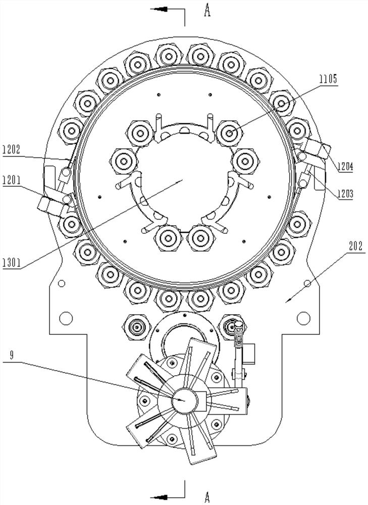
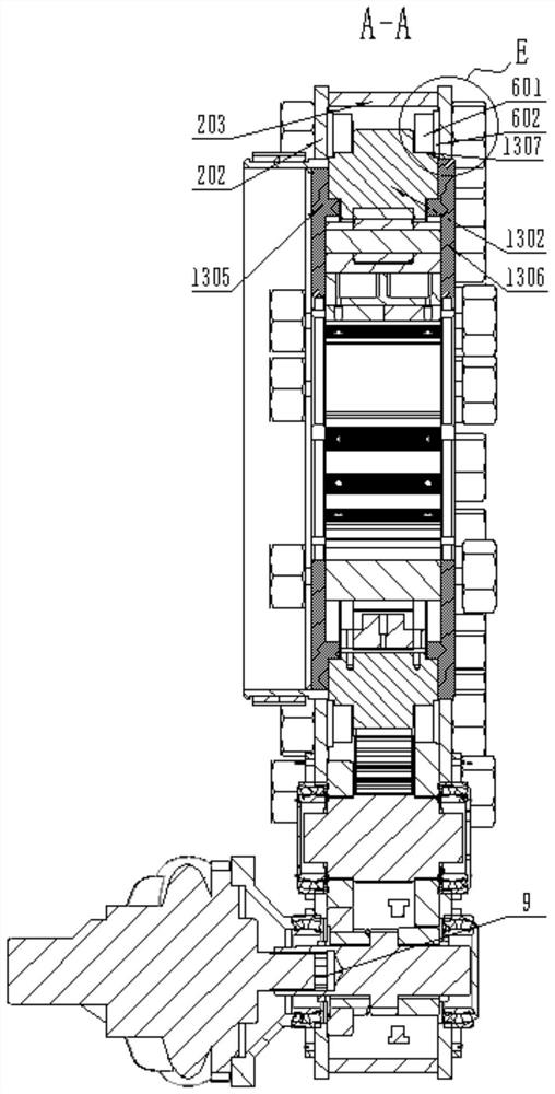
[0056] See attached Figure 1-13 , this instruct...


PUM


Abstract

The invention discloses a screwing mechanism which is used for centering and screwing a coupling pre-screwed on a steel pipe and comprises an annular rotating part driven by a driving device to rotate, and the inner wall of a shaft hole of the annular rotating part is provided with at least two outwards-sunken arc-shaped adjusting faces. Main clamp assemblies are installed in the shaft hole and are arranged in one-to-one correspondence with the arc-shaped adjusting faces, the near end of each main clamp assembly is in rolling connection with the arc-shaped adjusting faces, and the far end of each main clamp assembly is arranged in a sliding mode in the radial direction under the matching action of a limiting mechanism and the arc-shaped adjusting faces, so that the main clamp assemblies can have a coupling clamping state or a receding state. The mechanism at least has the following advantages that centering clamping and screwing of the coupling can be achieved, and meanwhile, the coupling can be prevented from being damaged due to too large screwing force in the mode.

Description

technical field [0001] The invention relates to the technical field of collar tightening, in particular to a screwing mechanism and a collar centering screwing device. Background technique [0002] The statements in this section only provide background information related to the present disclosure and may not constitute prior art. [0003] The coupling is a kind of oilfield drilling tool, which mainly provides connection for the oil casing and oil pipe used in the downhole through the threads at both ends of the coupling. Usually, the seamless steel pipe used in the oil field is screwed on one end of the steel pipe with a coupling before leaving the factory, and the other end is only provided with a protective sleeve for the thread. When drilling in the oil field, the thread at the end with the protective sleeve is screwed into the coupling of the previous steel pipe. Inside, they are connected in turn to form the well wall of the oil well. [0004] The existing coupling t...

Claims


Application Information

Patent Timeline
Patent Type & Authority Applications(China)
IPC IPC(8): E21B19/16
CPCE21B19/161
Inventor 仓国玉胡希源
Owner 盐城保源自动化设备有限公司
Why Eureka
Try Eureka