A Conformal Diffuser Combining Radial and Axial Diffusers

A diffuser, axial technology, applied in the direction of machines/engines, pumping devices for elastic fluids, liquid fuel engines, etc., can solve the problem that the diffuser cannot have too long radial blades and the application range is limited Limitation and other problems, to achieve the effect of suppressing flow separation, ensuring continuity and increasing friction loss

Active Publication Date: 2022-07-12
DALIAN UNIV OF TECH
View PDF9 Cites 1 Cited by
  • Summary
  • Abstract
  • Description
  • Claims
  • Application Information

AI Technical Summary

Problems solved by technology

However, due to this fusion method, the diffuser itself cannot have too long radial blades, so the ratio of the inlet diameter of the diffuser must be controlled below 1.3, which limits its application range

Method used


Image

  • A Conformal Diffuser Combining Radial and Axial Diffusers
  • A Conformal Diffuser Combining Radial and Axial Diffusers
  • A Conformal Diffuser Combining Radial and Axial Diffusers

Examples


Embodiment Construction

[0026] The present invention will be described in detail and concretely below through specific embodiments, so as to make the present invention better understood, but the following embodiments do not limit the scope of the present invention.

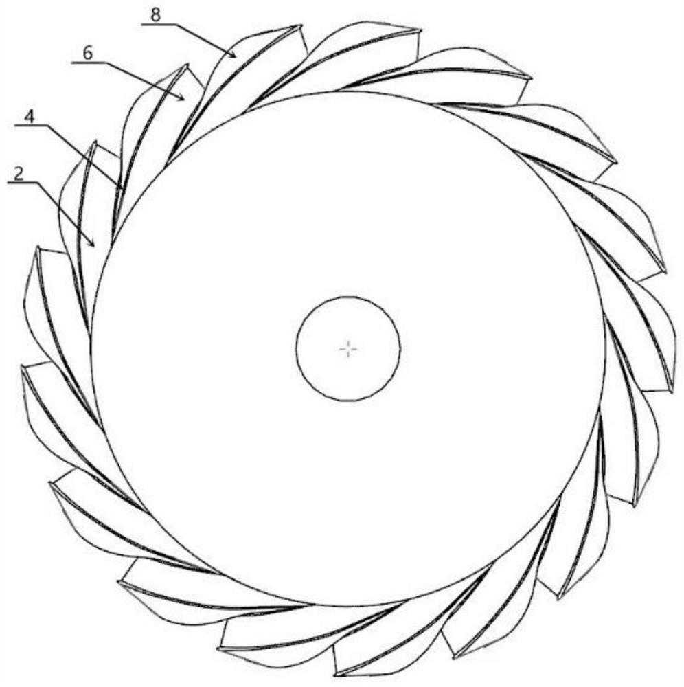
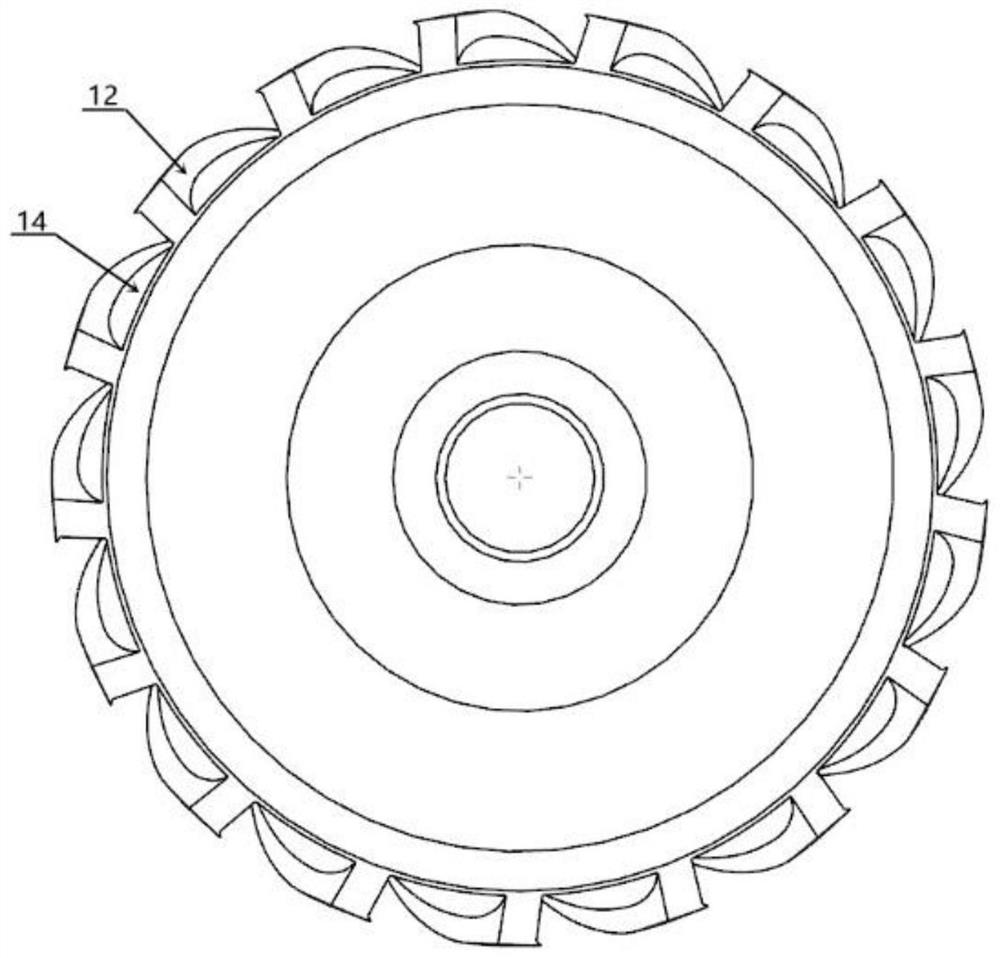
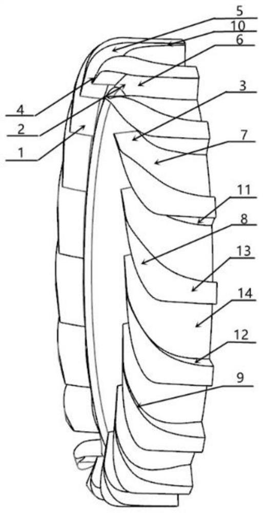
[0027] like Figure 1 to Figure 8 As shown, a radial and axial diffuser of the present invention is a centrifugal compressor conformal diffuser structure, the conformal diffuser includes an inner casing and blades; The structure is complex and the size is small, so 3D printing is recommended. The diffuser vanes are evenly distributed along the circumferential direction of the diffuser according to the required number, and the airflow passage in the diffuser is formed between the two adjacent vanes. Each diffuser vane includes a radial segment, a turning segment and an axial segment integrally constructed. The front end of the radial section of the diffuser vane is wedge-shaped, the thickness of the vane is small, and the leading edge i...


PUM


Abstract

The invention discloses a shape-preserving diffuser which is fused with radial and axial diffusers. The diffuser is particularly suitable for an aviation centrifugal compressor with limited radial and axial dimensions. It has the following two key technologies: 1. The radial section, the turning section and the axial section of the vane diffuser are integrated into the design. 2. The radial section of the diffuser is similar to a wedge-shaped diffuser. Starting from the turning section, a part of the blades and the inner casing begin to merge with each other, and finally this part of the blades is converted into the inner casing and the radial wall is converted into the blade surface . This design method enables the diffuser to ensure that the airflow direction is converted from radial to axial under the condition that the radial and axial dimensions are constrained, and each section of the diffuser has a good degree of diffusion. Therefore, the air flow will not separate in the flow channel, reducing the flow loss in the diffuser and improving the overall performance of the compressor.

Description

technical field [0001] The patent of the invention belongs to the technical field of centrifugal compressors, and relates to a novel diffuser structure. The structure achieves the purpose of rapidly transforming the airflow direction from radial to axial through the mutual fusion of radial vanes and axial vanes, and is especially suitable for aeronautical centrifugal compressors with limited radial dimensions. Background technique [0002] With the increasing thrust-to-weight ratio of aero-engines, compact high-pressure ratio centrifugal compressors have received extensive attention. The higher the pressure ratio of the centrifugal compressor, the higher the Mach number of the airflow at the centrifugal impeller outlet. The high Mach number inflow brings serious challenges to the diffuser design, especially when the radial size of the unit is limited. [0003] In the prior art, in micro-centrifugal compressors, the radial section, turning section and axial section of the d...

Claims


Application Information

Patent Timeline
Patent Type & Authority Patents(China)
IPC IPC(8): F02C3/08F04D29/44F01D9/04
CPCF02C3/08F04D29/444F01D9/041Y02W10/10
Inventor 杨秀鑫杨金广刘艳
Owner DALIAN UNIV OF TECH
Why Eureka
Try Eureka