Transmission mechanism for drive unit

A transmission mechanism and drive unit technology, applied to transmission parts, mechanical equipment, belts/chains/gears, etc., to achieve the effects of minimizing agitation losses, benefiting efficiency, and saving structural space and materials or weight

Pending Publication Date: 2021-12-07
ROBERT BOSCH GMBH
View PDF2 Cites 0 Cited by
  • Summary
  • Abstract
  • Description
  • Claims
  • Application Information

AI Technical Summary

Problems solved by technology

The oil guide requires a relatively large amount of space in the interior of the transmission arrangement

Method used


Image

  • Transmission mechanism for drive unit
  • Transmission mechanism for drive unit
  • Transmission mechanism for drive unit

Examples


Embodiment Construction

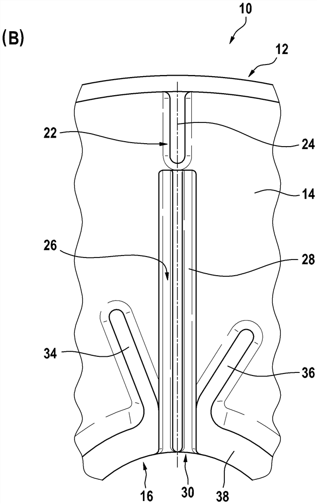
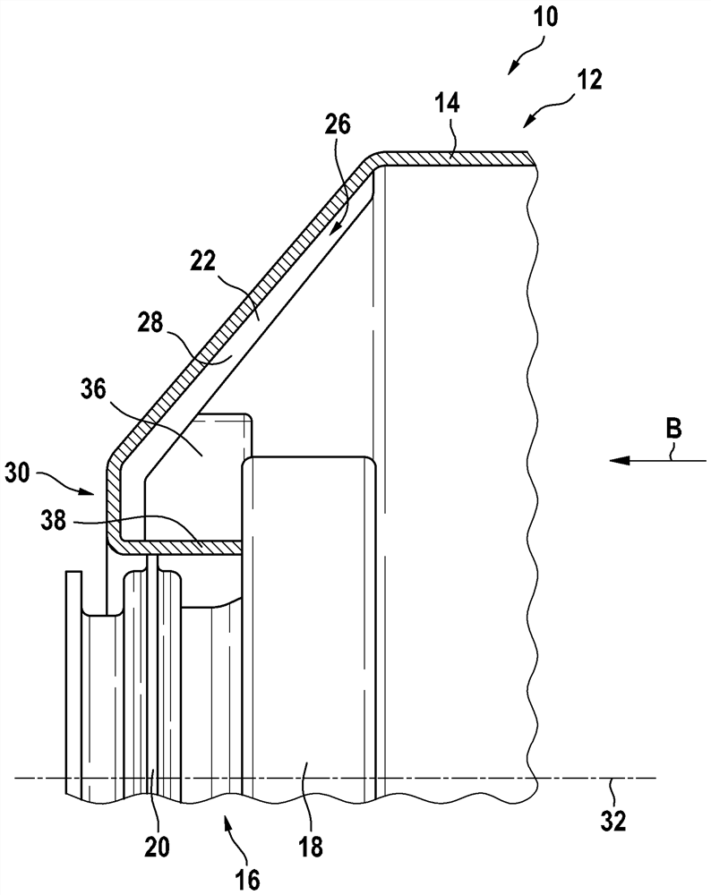
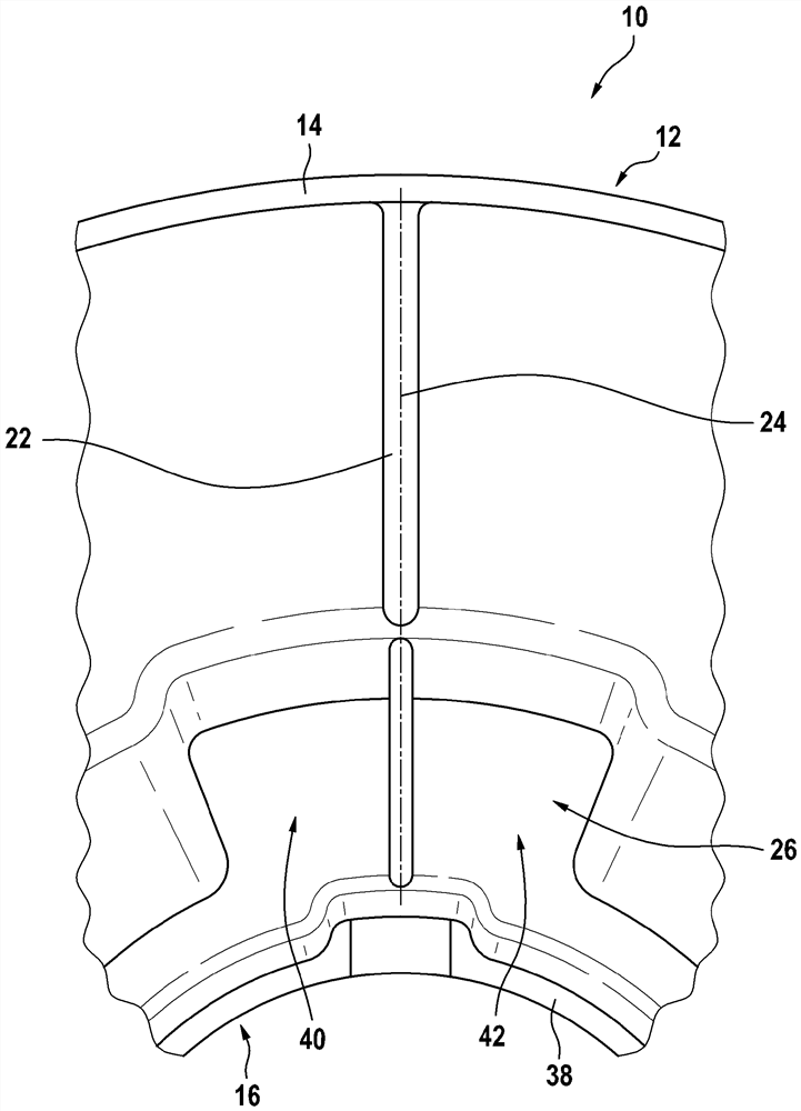
[0025] exist figure 1 and figure 2 In , a transmission for a drive unit of a vehicle generally bears the reference numeral 10 .

[0026] The transmission 10 has a transmission housing 12 with a wall 14 . A seat 16 for a rolling bearing 18 and / or a radial shaft sealing ring 20 is formed in the wall 14 . In this example, the rolling bearing 18 and the radial shaft sealing ring 20 are inserted into the carrier 16 (see figure 1 ).

[0027] Scraper ribs 22 protruding from the wall 14 are formed on the wall 14 and extend along a central longitudinal axis 24 (cf. figure 2 ). The central longitudinal axis 24 of the scraper rib 22 intersects (in its extension) the seat 16 for the rolling bearing 18 and / or the radial shaft sealing ring 20 . Between the scraper rib 22 and the seat 16 a recess 26 is formed in the wall, which extends between the scraper rib 22 and the seat 16 .

[0028] The transmission 10 can have further components, for example a transmission shaft with toothing...


PUM


Abstract

The invention relates to a transmission mechanism (10) for a drive unit of a vehicle. The transmission mechanism has a transmission housing (12) with a wall (14), a bearing (16) for a rolling bearing (18) and/or a radial shaft sealing ring (20) being formed in the wall (14). According to the invention, a scraping rib (22) protruding from the wall (14) is formed on the wall (14), the scraping rib extending along a central longitudinal axis (24), the central longitudinal axis (24) of the scraping rib (22) intersects the support (16), and one or more recesses (26) are formed in the wall (14) between the scraping rib (22) and the support (16), the recesses extend between the scraping rib (22) and the support (16).

Description

technical field [0001] The invention relates to a transmission for a drive unit of a vehicle according to the preamble of claim 1 . Background technique [0002] A transmission of this type is known, for example, from DE 10 2019 100 315 A1, which discloses a drive unit for a vehicle with an electric motor and a transmission. An oil supply unit is provided therein, by means of which the electric motor, the transmission and the inverter for actuating the electric motor can be supplied with oil, wherein the oil is delivered by means of an oil pump. This leads to high structural and economical outlay. [0003] DE 10 2012 202 453 B4 discloses a transmission arrangement with an oil guide system, on which the oil quantity contained is sprayed by means of an oil immersion wheel (Öltauchrad) and distributed over several oil guides collect. Oil guides require a relatively large amount of space within the transmission arrangement. Contents of the invention [0004] The problem un...

Claims


Application Information

Patent Timeline
Patent Type & Authority Applications(China)
IPC IPC(8): F16H57/04
CPCF16H57/0424F16H57/0471F16H57/0472F16C19/06F16H57/029F16C2361/61
Inventor J·克劳特M·萨雷茨基
Owner ROBERT BOSCH GMBH
Why Eureka
Try Eureka