Offset type starting vector sealing valve

A biased, vector technology, applied in the direction of valve lift, valve details, valve device, etc., can solve the problem of failure to achieve point break, point repair, interruption or paralysis of pipeline network trunk system, loss of resources such as material resources and media and other problems, to achieve the effect of compact structure, easy processing, and reduced assembly accuracy

Pending Publication Date: 2021-12-07
GUIZHOU NAIHENG TECH CO LTD
View PDF0 Cites 1 Cited by
  • Summary
  • Abstract
  • Description
  • Claims
  • Application Information

AI Technical Summary

Problems solved by technology

Unable to achieve point break and point repair (or replacement) operations, resulting in the loss of a lot of manpower, material resources and media resources, and thus causing the interruption or paralysis of the main pipe network or other systems
[0003] Chinese patent application (application number 2019112794029) discloses a vector seal valve, which includes a valve body, a valve plate and a valve shaft, the valve plate is rotatably connected to the valve body through a valve shaft fixedly connected to it, the valve The axial half of the inner cavity of the body is set as a hemispherical cavity, and the other half of the inner cavity is a cylindrical cavity. The vector sealing ring is embedded in the cylindrical cavity. The inner surface of the vector sealing ring and the hemispherical cavity of the valve body form a spherical section cavity. The surface is consistent with the spherical cross-section cavity. This structure is directly driven by the valve shaft, and the driving force is large. For the opening and closing of large valves, the required torque is large.

Method used


Image

  • Offset type starting vector sealing valve
  • Offset type starting vector sealing valve
  • Offset type starting vector sealing valve

Examples


Embodiment 1

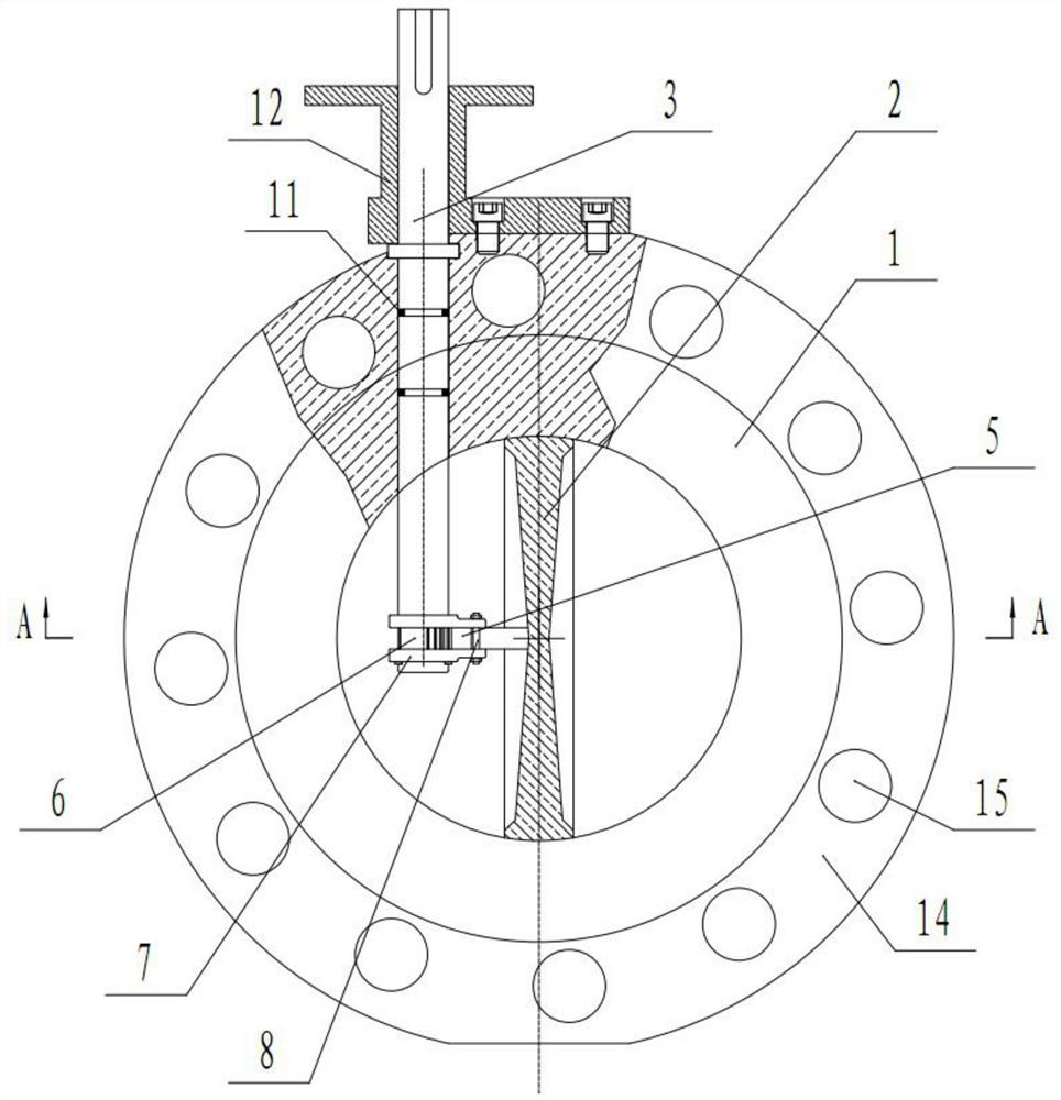
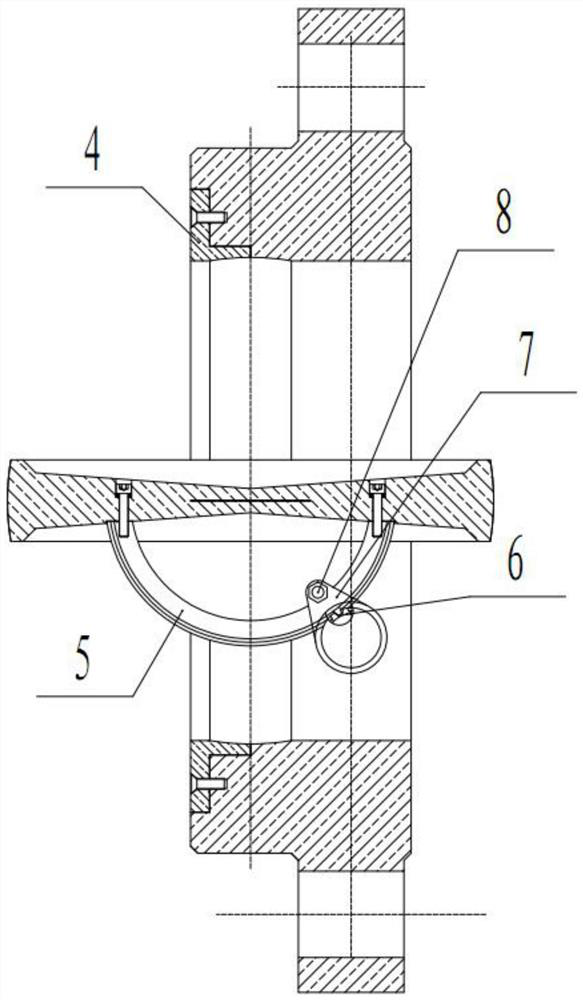
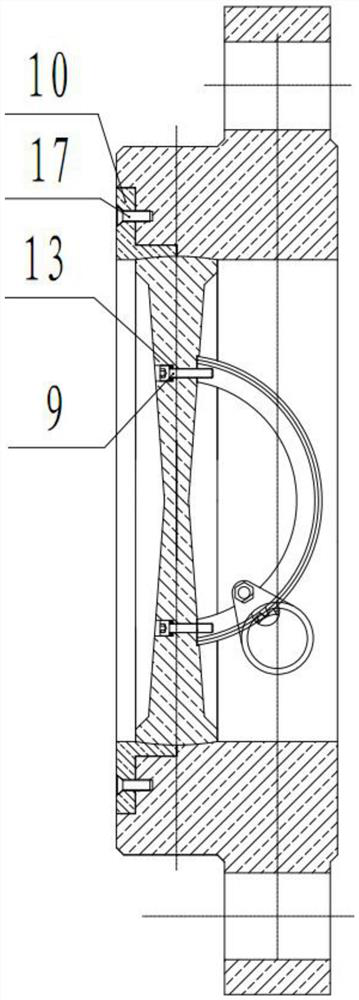
[0036] Embodiment 1: as Figure 1-8 As shown, a biased starting vector seal valve includes a valve body 1, a valve plate 2 and a valve shaft 3, the valve plate 2 is rotatably connected to the valve body 1, and the axial half of the valve body 1 is set It is a hemispherical cavity, and the other half of the inner cavity is a cylindrical cavity. The vector sealing ring 4 is embedded in the cylindrical cavity. The inner surface of the vector sealing ring 4 and the hemispherical cavity of the valve body 1 form a spherical section cavity. The cross-section cavity is the same, the center symmetry of one side of the valve plate 2 is axially fixedly connected with a sector gear 5, and the driving gear 6 meshing with the sector gear 5 is fixedly connected to the valve shaft 3, and the valve shaft 3 is rotatably connected to the valve body 1 and is biased. Set a distance from the center of the valve plate 2 (the axis of the valve shaft intersects with the axis of the valve plate or the ...


PUM


Abstract

The invention discloses an offset type starting vector sealing valve which comprises a valve body, a valve plate and a valve shaft. The valve plate is rotatably connected to the valve body, an axial half inner cavity of the valve body is a hemispherical cavity, the other half inner cavity of the valve body is a cylindrical cavity, a vector sealing ring is embedded in the cylindrical cavity, and the inner surface of the vector sealing ring and the hemispherical cavity of the valve body form a spherical section cavity. The radial outer side surface of the valve plate is consistent with the spherical section cavity, the center of one side of the valve plate is symmetrically and fixedly connected with a sector gear in the axial direction, a driving gear meshing with the sector gear is fixedly connected to the valve shaft, and the valve shaft is rotationally connected to the valve body and deviates from the center of the valve plate by a certain distance. The spherical surface of the valve plate is thoroughly in full self-positioning contact with the spherical section cavity of the valve body, complete spherical surface rigid sealing is achieved, the sealing effect is better, and the axial bearing capacity is better; the assembly precision is reduced, the installation of the valve is more convenient, and the installation difficulty is reduced; and offset starting is adopted, the starting torque is reduced, and more labor is saved or the power of a driving motor is reduced.

Description

technical field [0001] The invention belongs to the technical field of valves, and in particular relates to a biased starting vector sealing valve. Background technique [0002] At present, there are many types of valves used domestically and internationally, most of which are valves with butterfly valves, ball valves, and gate valves as the main structure and structure. Most of this type of valves are bulky and heavy; the installation size is long; the sealing effect is poor; the opening and closing torque and torque requirements are large; the use of electric or pneumatic actuators and other transmission methods requires a large power for opening and closing; the service life It is short and contradicts with the current specifications and standards of various valve wells and chambers in the use environment. Often a large-diameter valve is installed in a small valve well or chamber (inside) or the valve is installed first and then the well, room, which highlights the contr...

Claims


Application Information

Patent Timeline
Patent Type & Authority Applications(China)
IPC IPC(8): F16K1/226F16K31/53F16K27/02
CPCF16K1/2263F16K1/2268F16K31/535F16K27/0218
Inventor 张振民张宗普颜廷波
Owner GUIZHOU NAIHENG TECH CO LTD
Why Eureka
Try Eureka