Real vehicle testing method and device for driver state monitoring system

A driver status and monitoring system technology, applied in the automotive field, can solve problems such as insufficient actual performance

Pending Publication Date: 2021-12-07
FAW CAR CO LTD
View PDF0 Cites 0 Cited by
  • Summary
  • Abstract
  • Description
  • Claims
  • Application Information

AI Technical Summary

Problems solved by technology

[0003] The present invention provides a real-vehicle test method and device for a driver's state monitoring system. By obtaining the driver's facial movement feature collection and the CAN bus signal inside the vehicle, combined with the specific test conditions of the proposed method, the test data is obtained to judge the driver's state monitoring The functional performance of the system can improve the accuracy of the test of the driver's state monitoring system in the real vehicle environment, and solve the problems of idealization and insufficient actual performance brought about by the simulation test.

Method used


Image

  • Real vehicle testing method and device for driver state monitoring system
  • Real vehicle testing method and device for driver state monitoring system
  • Real vehicle testing method and device for driver state monitoring system

Examples


Embodiment 1

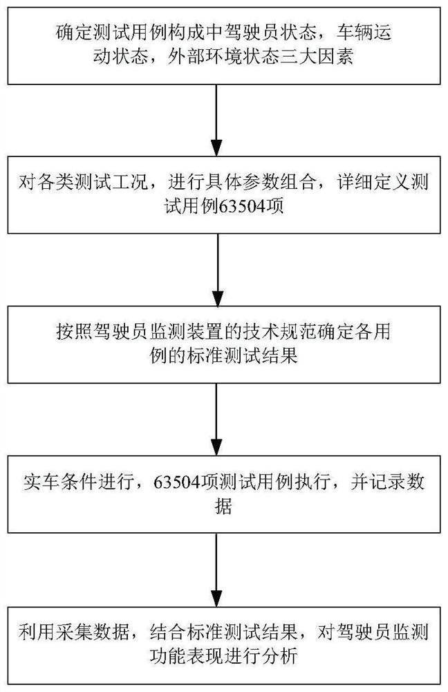
[0029] refer to figure 1 , a kind of actual vehicle testing method of driver state monitoring system, comprises the following steps:

[0030] Step 1. Determine the three major factors of the real vehicle test;

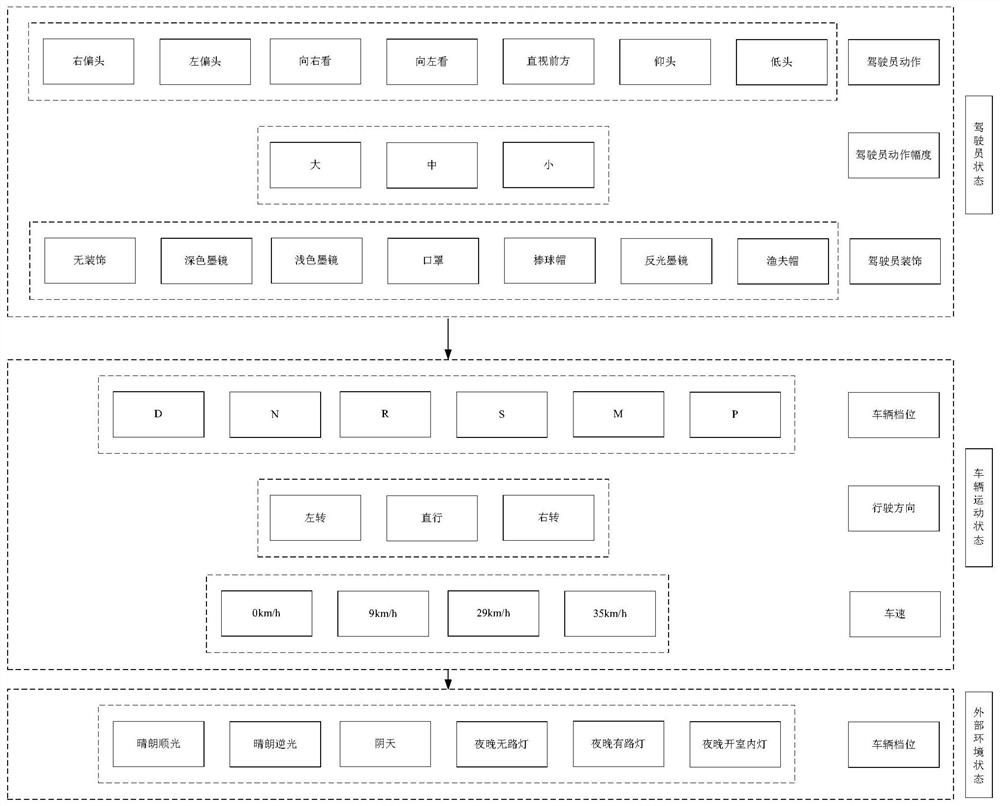
[0031] refer to figure 2 , the three major factors include driver state, vehicle motion state and external environment state;

[0032] The state of the driver includes three parameter variables of driver action, action range and driver decoration;

[0033] The driver's actions include: tilting the head to the right, tilting the head to the left, looking right, looking left, looking straight ahead, raising the head, and lowering the head.

[0034] The range of motion includes large, medium and small.

[0035] The driver's accessories include no decoration, dark sunglasses, light sunglasses, masks, baseball caps, reflective sunglasses, and bucket hats.

[0036] The vehicle motion state includes three parameter variables of vehicle gear, driving direction and vehicl...

Embodiment 2

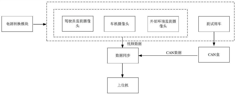
[0051] refer to image 3 , a real-vehicle test device for a driver state monitoring system, used to implement a real-vehicle test method for a driver state monitoring system, comprising:

[0052] The setting module is used to set the three major factors of the real vehicle test;

[0053] The combination module is used to arrange and combine the three major factors to form test cases;

[0054] The standard test result module is used to determine the correct standard test result of each test case according to the technical specification of the driver monitoring system;

[0055] The test module is used to execute each test case, test the driver state monitoring system, and record the test results;

[0056]The test module includes a driver state monitoring camera, a car machine monitoring camera, an external environment monitoring camera, and a car CAN box tool; the driver state monitoring camera is used to collect the driver's state; the car machine monitoring camera, It is us...


PUM


Abstract

The invention relates to a real vehicle testing method and device for a driver state monitoring system. The testing method comprises the following steps: 1, determining three factors of real vehicle testing; 2, defining a test case by combining three factors of a real vehicle test; 3, determining a correct standard test result of each use case according to a technical specification of a driver monitoring system so as to obtain a test evaluation index; 4, executing each test case, testing the driver state monitoring system, and recording a test result; 5, analyzing the function performance of the driver monitoring system according to the test result obtained in the step 4 in combination with the standard test result obtained in the step 3. According to the driver state monitoring system testing method, the driver face action characteristics are acquired, the CAN bus signals in the vehicle are acquired, the specific testing working conditions of the method are combined, the testing data are acquired to judge the function performance of the driver state monitoring system, and the testing accuracy of the driver state monitoring system in the real vehicle environment can be improved.

Description

technical field [0001] The invention belongs to the technical field of automobiles, and in particular relates to a method and device for a real vehicle test of a driver state monitoring system. Background technique [0002] With the development of automotive intelligent network technology, more and more car manufacturers are equipped with intelligent network configuration in their products, and the driver status monitoring function, as an intelligent network function, is also gradually launched on the market. Before the vehicle goes on the market, it is necessary to complete the test and verification of the functional integrity, reliability and performance indicators of the driver status monitoring function. At present, most of the test verifications for the driver status monitoring system are carried out by means of simulated robots and light simulation. This kind of test is too idealistic, lacks the authenticity of the scene, and cannot directly give the functional perfor...

Claims


Application Information

Patent Timeline
IPC IPC(8): G06F11/36
CPCG06F11/3688G06F11/3692
Inventor 孙运玺王升鑫王晰聪刘德利王邵龙赵跃谷原野王洪超马文峰孙云
Owner FAW CAR CO LTD
Why Eureka
Try Eureka