Constant-current charging circuit for super capacitor

A supercapacitor, constant current charging technology, applied in battery circuit devices, circuit devices, battery overcurrent protection, etc., can solve the problems of increased cost, high cost, and large size of linear circuits, and achieve the effect of making up for the impact.

Pending Publication Date: 2021-12-07
上海稊米汽车科技有限公司
View PDF0 Cites 1 Cited by
  • Summary
  • Abstract
  • Description
  • Claims
  • Application Information

AI Technical Summary

Problems solved by technology

[0003] The traditional step-down constant current charging circuit basically adopts two methods, one is the PWM control method, such as BUCK, BUCK-BOOST and other topological structures, for the charge and discharge management of small-capacity supercapacitors (supercapacitors with a capacity less than 20F In terms of capacity), its radiation and conduction need to spend a relatively high cost to meet the requirements of automotive electronics, and the volume is relatively large, which is not an ideal solution; the other is a linear charging circuit, which has obvious disadvantages. When charging from 0V, the voltage drop from the input voltage to the output voltage is relatively large, and the voltage drop and loss are all borne by the linear circuit, so the loss of the linear circuit is a big problem. At the same time, a relatively large heat sink is required, so the volume and heat dissipation become A problem, and the cost of the linear circuit will increase exponentially with the rise of the charging current, which cannot meet the needs of customers

Method used


Image

  • Constant-current charging circuit for super capacitor
  • Constant-current charging circuit for super capacitor
  • Constant-current charging circuit for super capacitor

Examples


Embodiment Construction

[0022] The specific implementation manner of the present invention will be described in detail below in conjunction with the accompanying drawings and preferred implementation examples.

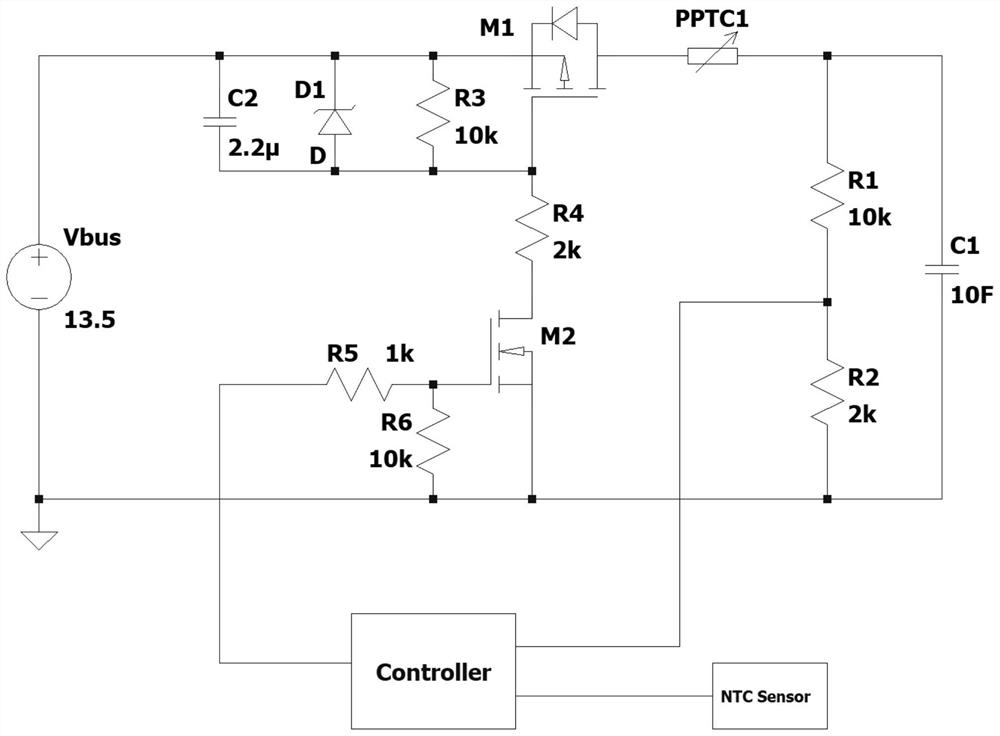
[0023] First, let's introduce the working principle of the basic step-down constant current charging circuit. The circuit structure is as follows: figure 1 As shown, resistors R1 and R2 form a supercapacitor such as a voltage acquisition module of a supercapacitor, field effect transistors M1 and M2, Zener diode D1, resistors R3, R4, R5, R6, and buffer capacitor C2 form an enabling trigger module for a charging circuit , the processor Controller is used to collect external voltage, ambient temperature, current and other signals, and do corresponding logic control. The NTC sensor is used to collect the ambient temperature and transmit it to the processor controller. The working process is as follows:

[0024] After powering on for the first time, the processor first detects the voltage of the ...


PUM


Abstract

The invention belongs to the technical field of charging management, and discloses a constant-current charging circuit for a super capacitor. The circuit comprises a charging power supply, the charging power supply is connected with the super capacitor through a constant-current unit, and the constant-current unit comprises an enabling trigger module and a resettable fuse PPTC which are connected together. The two ends of the super capacitor are further connected with a voltage detection module in parallel, the voltage detection module is used for detecting voltage signals at the two ends of the super capacitor, the voltage detection module, the enabling trigger module and the temperature detection module are all connected with the processor, and the temperature detection module is used for detecting the environment temperature; the processor is used for controlling the resettable fuse PPTC to enter a high-resistance state through the enabling trigger module according to the received environment temperature and voltage signals, and constant-current charging of the super capacitor is carried out.

Description

technical field [0001] The invention belongs to the technical field of charging management, and in particular relates to a constant current charging circuit for supercapacitors. Background technique [0002] As the use of supercapacitors becomes more and more popular, the management of charging and discharging of supercapacitors becomes more and more important, especially in the field of automotive electronics, the performance requirements for the charging circuit of supercapacitors are very high, which requires extremely low radiation and conduction disturbance level, and requires low price and small size, so various new low-cost charging circuit applications are born. [0003] The traditional step-down constant current charging circuit basically adopts two methods, one is the PWM control method, such as BUCK, BUCK-BOOST and other topological structures, for the charge and discharge management of small-capacity supercapacitors (supercapacitors with a capacity less than 20F ...

Claims


Application Information

Patent Timeline
Patent Type & Authority Applications(China)
IPC IPC(8): H02J7/00H02J7/34
CPCH02J7/00714H02J7/00304H02J7/00309H02J7/345
Inventor 张献辉许伟泉周程荀海波尹秋帆莫永聪
Owner 上海稊米汽车科技有限公司
Why Eureka
Try Eureka