Outer rotor brushless motor heat dissipation assembly

A brushless motor and heat-dissipating component technology, which is applied to electric components, motors, electrical components, etc., can solve the problems of small heat-dissipating range, poor heat-dissipating effect, slow wind flow of fan blades, etc., and achieve the effect of increasing heat-dissipating effect and stable and reliable water supply.

Active Publication Date: 2021-12-07
安徽智鸥驱动科技有限公司
View PDF4 Cites 4 Cited by
  • Summary
  • Abstract
  • Description
  • Claims
  • Application Information

AI Technical Summary

Problems solved by technology

In the present invention, the inner sides of the end covers on both sides of the motor are respectively designed as axial-flow and centrifugal fan blades, so that the heat generated by the motor is forcibly taken away by the wind flow that enters and exits the motor during the working process, ensuring the motor's stability. Effective heat dissipation, but the following problems exist in the above structure. For some low-speed high-torque motors, they also generate more heat when they work, and because of their low speed, if the heat dissipation mechanism is designed like this, the air flow generated by the fan blades will be too slow. , the heat dissipation effect is extremely poor;
[0004] Patent CN201820043887.6 discloses a DC outer rotor brushless motor liquid cooling structure, the DC outer rotor brushless motor liquid cooling structure is simple, the external power supply is connected, the rotating motor is started, and the circular turntable is driven to rotate. The connecting rod hinged on the edge of the front side wall of the turntable drives the piston to reciprocate horizontally in the hydraulic cylinder; when the piston moves to the right, the cooling water in the water tank enters the inner cavity of the hydraulic cylinder through the third connecting pipe; when the piston moves to the left, the hydraulic pressure The cooling water in the inner cavity of the cylinder pushes the ball away from the water inlet of the first spring tube, and enters the water cooling part through the water inlet pipe. The water enters the water tank through the second connecting pipe for cooling. The combination of the two, through the flow of water, the large amount of heat generated by the operation of the DC outer rotor brushless motor body greatly improves the practicability, but the rotor part is only used for heat exchange and heat dissipation by water cooling. , the heat dissipation range is small, and the heat dissipation effect is poor

Method used


Image

  • Outer rotor brushless motor heat dissipation assembly
  • Outer rotor brushless motor heat dissipation assembly
  • Outer rotor brushless motor heat dissipation assembly

Examples


Embodiment 1

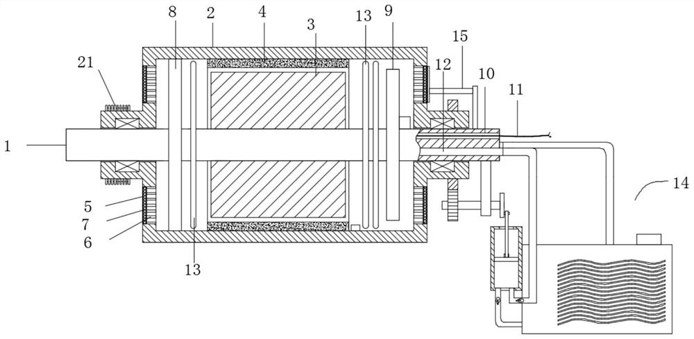
[0037]as attached Figure 1-3 As shown, the present invention provides a kind of technical scheme:

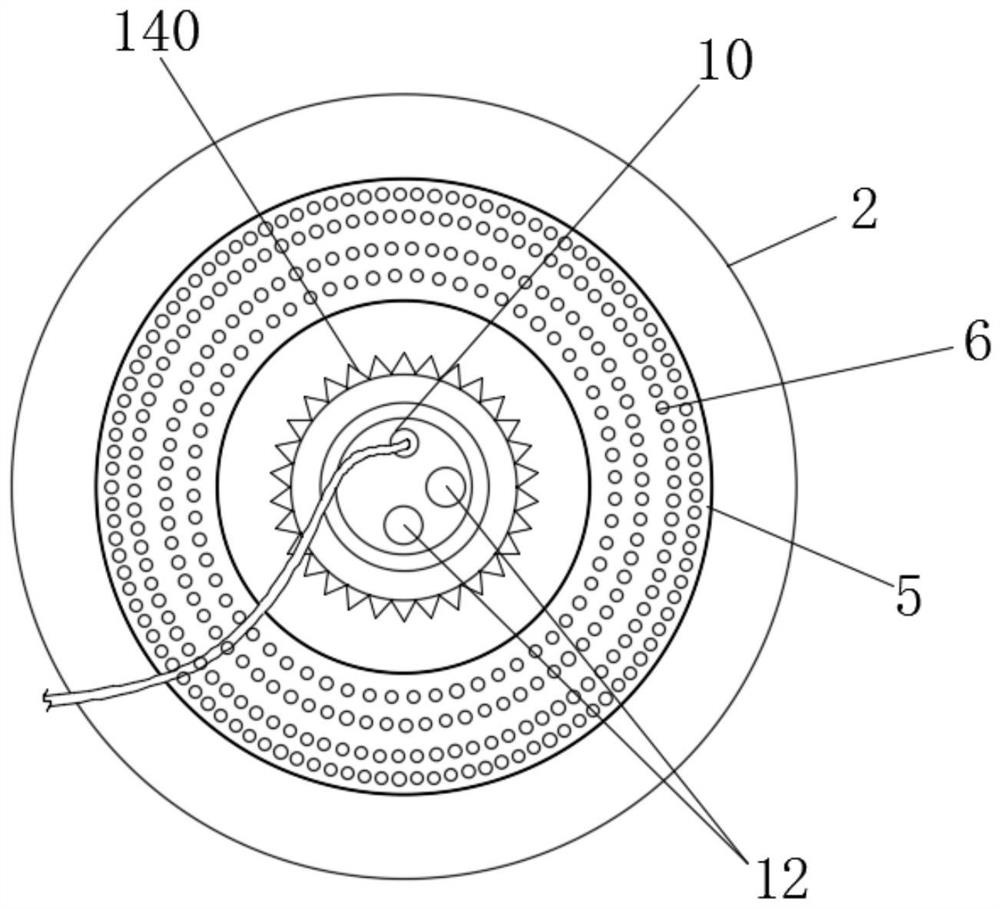
[0038] Outer rotor brushless motor heat dissipation assembly, including motor shaft 1, casing 2, stator 3 and rotor 4, the left and right ports of casing 2 are fixedly installed on motor shaft 1 through bearings, stator 3 is fixedly installed on motor shaft 1, stator 3 A rotor 4 is arranged on the periphery, and the rotor 4 is fixedly installed in the middle part of the inner side of the casing 2. A pulley 21 is installed on the protruding nozzle on the left side of the casing 2. A cable channel 10 is opened in the motor shaft 1, and a cable channel 10 is provided in the cable channel 10 to connect the stator 3. The power supply cable 11, the left and right ends of the casing 2 are provided with air holes 6 correspondingly, the inner cavity of the casing 2 is fixed with an exhaust impeller 8, the exhaust impeller 8 is located on the left side of the stator 3, and the motor shaf...

Embodiment 2

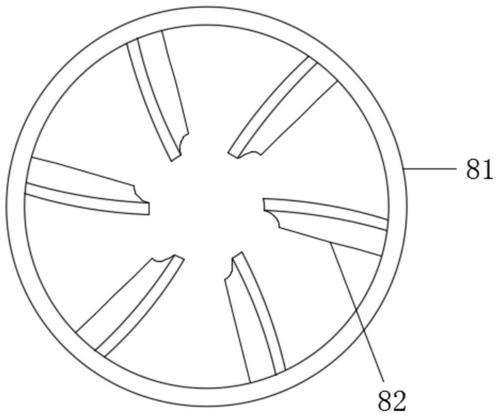
[0046] Such as Figure 4 and Figure 5 Shown, under the situation that other parts are all identical with embodiment 1, the difference of this embodiment and preceding embodiment is:

[0047] The electric drive cooling fan blade 9 includes a blower fan blade and a driving part, and the blower fan blade includes a fan blade cover seat 91, and the fan blade cover seat 91 is fixedly installed on the motor shaft 1 through a bearing, and the fan blade cover seat 91 is provided with a fan blade 92 , one side of the center hole of the fan blade cover 91 is provided with a protruding part 93, and a first gear 94 is installed on the protruding part 93;

[0048] The driving part includes a fan blade motor 95 fixedly installed on the motor shaft 1, a second gear 96 is arranged on the output shaft of the fan blade motor 95, and the second gear 96 is meshed with the first gear 94. The power supply circuit of the fan blade motor 95 Connect with the external power supply through the cable ...

Embodiment 3

[0051] Such as Figure 6 As shown, under the situation that other parts are all the same as the foregoing embodiments, the difference between this embodiment and the foregoing embodiments is:

[0052] The heat exchange tube 13 includes several groups of circular tubes 131 with different diameters. All the circular tubes 131 are arranged concentrically. The circular tubes 131 are fixedly connected by connecting pieces 132 . , the inlet and outlet of the innermost circular tube 131 are respectively connected with the water inlet channel and the water outlet channel. During condensation work, the condensed water enters from the inner circular tube 131 and gradually spreads to the outer circular tube 131, and finally passes through the outermost circular tube. The backflow pipeline 134 on the 131 enters the back row of the water outlet channel.

[0053] In this embodiment, a heat exchange tube structure is specifically designed, which is a mosquito-repellent incense structure, th...


PUM


Abstract

The invention relates to the technical field of motor heat dissipation, in particular to an outer rotor brushless motor heat dissipation assembly which comprises a motor shaft, a shell, a stator and a rotor, the left end opening and the right end opening of the shell are fixedly installed on the motor shaft through bearings, the stator is fixedly installed on the motor shaft, and the rotor is arranged on the periphery of the stator. The rotor is fixedly installed in the middle of the inner side of the shell, and a belt wheel is installed on a protruding pipe opening in the left side of the shell. Different from the prior art, according to the invention, the fan blades on the right side are improved to be electrically-driven heat dissipation fan blades, the rotating speed of the fan blades is not related to the rotating speed of the brushless motor, the fan blades are independently driven, the rotating speed of the fan blades can be adjusted according to needs to change the air inlet flow speed, and different heat dissipation effects are achieved; and according to the invention, the heat exchange pipes are arranged on the two sides of the motor shaft, and air cooling is combined, so that the air flow entering the shell is cooled, heat is directly taken away through the low-temperature air flow while cooling is conducted through heat exchange, and the heat dissipation effect of liquid cooling is greatly improved through the design mode.

Description

technical field [0001] The invention relates to the technical field of motor heat dissipation, in particular to a heat dissipation assembly of an outer rotor brushless motor. Background technique [0002] Electric motors are the power source provider for almost all electric equipment. During the working process of the existing motor, a large amount of heat is generated, and the heat can cause the temperature rise of the motor, consume more energy and cause fires. Therefore, a fan is fixed at the shaft end of the motor, and the heat generated in the motor is taken away by the synchronous rotation of the fan and the motor shaft. However, in the application process, it was found that the temperature drop of the motor was not very obvious. The reason was that although the wind blown by the fan was blowing against the motor, the blowing could not form smooth convection, which caused The heat cannot be effectively discharged, which will affect the service life of the motor and c...

Claims


Application Information

Patent Timeline
Patent Type & Authority Applications(China)
IPC IPC(8): H02K9/06H02K9/193H02K9/20H02K5/18H02K5/20H02K5/10H02K7/116H02K11/25B08B1/00
CPCH02K9/06H02K9/193H02K9/20H02K5/18H02K5/207H02K5/203H02K5/10H02K7/116H02K11/25B08B1/002B08B1/008Y02T10/64
Inventor 陈凡崔德新张志峰
Owner 安徽智鸥驱动科技有限公司
Why Eureka
Try Eureka