Mining wireless communication relay method

A wireless communication and mining technology, applied in wireless communication, electrical components, etc., can solve the problems of large attenuation of wireless signal transmission, lack of redundant functions, and difficulty in ground antenna layout

Pending Publication Date: 2021-12-07
株洲信通智能科技有限公司
View PDF0 Cites 2 Cited by
  • Summary
  • Abstract
  • Description
  • Claims
  • Application Information

AI Technical Summary

Problems solved by technology

[0003] (1) The underground space is narrow, and the wireless electromagnetic wave propagates in the space, and it will encounter multiple reflections, so that the signal reaches the receiving end through multiple paths, so there is frequency selective fading
[0004] (2) The vertical and horizontal length of the mine can reach tens to hundreds of kilometers and the space is narrow, the roadway is inclined, there are turns and branches, the surface of the roadway is rough, and there are obstacles such as locomotives, and the transmission attenuation of wireless signals is large
Among them, the ground-penetrating communication system has problems such as large equipment volume, heavy weight, small channel capacity, large ground equipment power, difficult ground antenna layout, and one-way communication (the ground faces the underground), so it is not suitable for use as a coal mine underground wireless communication system; leakage The communication system has problems such as narrow bandwidth, poor anti-disaster ability, poor reliability caused by a large number of serial relays, and lack of redundant functions. Therefore, it is not suitable for underground wireless communication systems in coal mines; ) The communication system has problems such as the base station controller and the base station not being intrinsically safe explosion-proof, the system does not have redundant functions, the ability to resist disasters is poor, the bandwidth is narrow, and the maximum communication distance between the underground base station and the ground does not meet the requirements of underground communication greater than 10 kilometers.

Method used


Image

  • Mining wireless communication relay method
  • Mining wireless communication relay method
  • Mining wireless communication relay method

Examples


Embodiment Construction

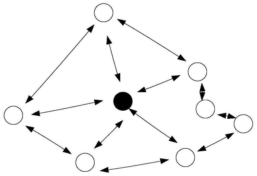
[0043] like figure 1 As shown, the present invention adopts the network topology of the MESH network. All devices in the network are full-featured devices, each node can be a coordinator, but only one node can be a coordinator. Each node in the network can talk to each other, and each node can become a relay for adjacent nodes. Therefore, this network form is very flexible, and the relay technology is relatively complicated. Before the device is powered on, the network does not exist, and the information in the relay table of each node is empty; when the device is powered on, the node with relay needs uses an on-demand relay algorithm to determine the network to reach the destination node Relay, and each node saves the generated relay information in the relay table. This kind of network can realize complex functions, and the network capacity is large, without additional relay equipment.

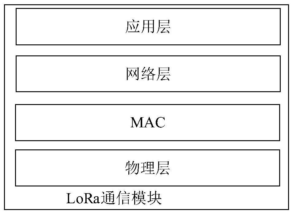
[0044] like figure 2 As shown, the LoRa communication protocol, which includes: phy...


PUM


Abstract

The invention discloses a mining wireless communication relay method. The method comprises the following steps: a network node needing to be relayed broadcasts a relay request message to surrounding nodes; each intermediate node records the address and the relay probability of the next hop in a relay table of the intermediate node; when the request information reaches a destination node through a certain path, an optimal path is selected according to relay probabilities of different paths; the destination node initiates a relay response, and returns to the source node through the optimal path. According to the invention, the relay probability algorithm in the MESH relay technology is realized. The nodes in the network have a relay function, and the problem that a relay needs to be additionally arranged in a star-shaped network architecture is solved. Under the powerful support of the grid-shaped network topology structure and all the full-function network nodes, all the nodes in the method have the ad hoc network function, along with the change of the environment, the nodes can flexibly select relays according to the relay probability between all the nodes, and it is guaranteed that the path is optimal at any time and in any environment.

Description

technical field [0001] The invention relates to a mine wireless communication network, in particular to a mine wireless communication network relay method, which is suitable for underground overhead passenger equipment and safety monitoring systems. Background technique [0002] Under the mine is a special working environment. The wireless channel under the mine is different from the general ground wireless communication channel, and has the following characteristics: [0003] (1) The underground space is narrow, and the wireless electromagnetic wave propagates in the space, and it will encounter multiple reflections, so that the signal reaches the receiving end through multiple paths, so there is frequency selective fading. [0004] (2) The length and width of the mine can reach tens to hundreds of kilometers and the space is narrow, the roadway is inclined, there are turns and branches, the surface of the roadway is rough, and there are obstacles such as locomotives, and t...

Claims


Application Information

Patent Timeline
Patent Type & Authority Applications(China)
IPC IPC(8): H04W40/22H04W40/24
CPCH04W40/22H04W40/246H04W40/248
Inventor 谷志茹陈顺科
Owner 株洲信通智能科技有限公司
Why Eureka
Try Eureka