
Intelligent material bin and machining center

An intelligent, silo technology, applied in metal processing, metal processing equipment, metal processing mechanical parts, etc., can solve the problems of low assembly efficiency, long occupation time, low production efficiency, etc., to improve production efficiency and reduce waiting time. Effect

Pending Publication Date: 2021-12-10
MAKINO MACHINE TOOL CHINA CO LTD
View PDF0 Cites 0 Cited by
  • Summary
  • Abstract
  • Description
  • Claims
  • Application Information

AI Technical Summary

Problems solved by technology

[0005] The purpose of the present invention is to provide an intelligent silo and machining center to solve the problem of low production efficiency caused by manual replacement of workpieces, low assembly efficiency and long time occupation

Method used


Image

  • Intelligent material bin and machining center
  • Intelligent material bin and machining center
  • Intelligent material bin and machining center

Examples


Embodiment 1

[0050]In the prior art, a machining center usually includes a machine tool and a tool library. The tool manipulator on the machine tool can communicate with the tool library to replace different tools, thereby realizing different processing techniques for the workpiece, shortening the auxiliary operation time of the workpiece, and improving the efficiency of the tool. Machining efficiency of complex workpieces. However, after the processing operation is completed, the staff needs to take out the finished workpiece from the outside, and then put the workpiece to be processed, so as to continue the processing. Since the staff may not be at the station temporarily, and the efficiency of manual assembly is low, the processing In the process of changing the workpiece, the center takes a long time, and the auxiliary operation time is long, which reduces the production efficiency of the machining center.

[0051] In order to solve the above problems, this embodiment provides a machin...

Embodiment 2

[0071] The difference between this embodiment and the first embodiment lies in that the structure of the machining center is different.

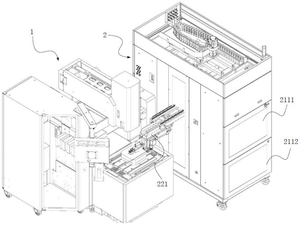
[0072] Specifically, in this embodiment, the machining center includes a pair of machine tools 1 and an intelligent storage bin 2 .

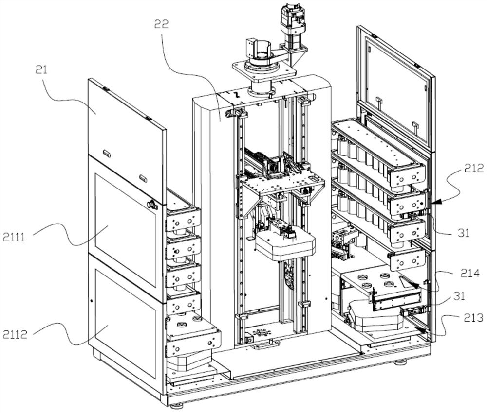
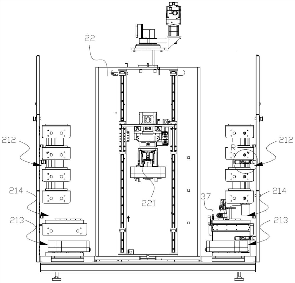
[0073] Wherein, the pair of machine tools 1 is a milling machine and an electric discharge machine. The cross-section of the material rack 21 is rectangular, and the transfer device 22 is arranged at the center of the material rack 21. A pair of relatively shorter sides of the material rack 21 are provided with a first placement area 212, a second placement area 213 and a second placement area 213. Three placement areas 214, the moving end of the transfer mechanism can be moved out of the material rack 21 by a pair of longer sides of the material rack 21, a milling machine and an electric discharge machine are respectively arranged on the outside of the material rack 21, and respectively Adjacent to a pair of...


PUM


Abstract

The invention belongs to the technical field of machining, and discloses an intelligent material bin. The intelligent material bin comprises a material frame, a transferring device arranged in the material frame and a suction and holding mechanism arranged at the moving end of the transferring device, and the moving end of the transferring device can move out of the material frame; the material frame comprises a first containing area capable of containing multiple cutters, a second containing area capable of containing multiple trays for bearing workpieces, a first safety door and a second safety door, the first safety door and the second safety door are arranged on the material frame, and the first containing area and the second containing area are both arranged in the material frame and located on the moving path of the transferring device; and the suction and holding mechanism can suck and hold the cutters and the trays, and the first safety door and the second safety door can be opened from the outer side of the material frame and communicate with the first containing area and the second containing area correspondingly. On the other hand, the invention discloses a machining center comprising a machine tool and the intelligent material bin. Workpieces do not need to be manually replaced for the machine tool, the waiting time in the material replacing process is shortened, and the production efficiency is improved.

Description

technical field [0001] The invention relates to the technical field of mechanical processing, in particular to an intelligent silo and a processing center. Background technique [0002] A machining center usually includes a machine tool and a tool library. The tool manipulator on the machine tool can communicate with the tool library to replace different tools, so as to realize different processing techniques of the workpiece, shorten the auxiliary operation time of the workpiece, and improve the processing efficiency of complex workpieces. . [0003] In the prior art, after the processing operation is completed, the staff needs to take out the processed workpiece from the outside, and then put in the workpiece to be processed, so as to continue processing, because the staff may not be at the station temporarily, and the efficiency of manual assembly is relatively low. Low, so that the machining center takes a long time in the process of changing workpieces, and the auxilia...

Claims


Application Information

Patent Timeline
Patent Type & Authority Applications(China)
IPC IPC(8): B23Q13/00B23Q7/00B23Q11/08B23Q17/00
CPCB23Q13/00B23Q7/008B23Q11/08B23Q17/00
Inventor 周阿威
Owner MAKINO MACHINE TOOL CHINA CO LTD
Features
  • Generate Ideas
  • Intellectual Property
  • Life Sciences
  • Materials
  • Tech Scout
  • Unparalleled Data Quality
  • Higher Quality Content
  • 60% Fewer Hallucinations
Learn More