Medical planer test system and test method

A test system and planing technology, applied in the field of testing, can solve problems such as low efficiency, inability to meet special test requirements, etc., to achieve a wide range of applications, achieve load characteristics and efficiency testing, and real test results.

Active Publication Date: 2022-04-08
SUZHOU YINGTUKANG MEDICAL TECH CO LTD
View PDF5 Cites 0 Cited by
  • Summary
  • Abstract
  • Description
  • Claims
  • Application Information

AI Technical Summary

Problems solved by technology

Manual short-duration testing is inefficient during high-speed load testing
In addition, due to its particularity, medical planers often require special tests in the actual development and research process, while dynamometers can only meet routine tests and cannot meet special test requirements

Method used


Image

  • Medical planer test system and test method
  • Medical planer test system and test method
  • Medical planer test system and test method

Examples


Embodiment 1

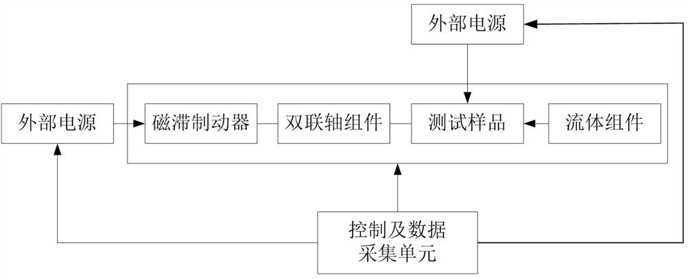
[0047] Considering the use environment of the medical planer and its structural particularity, refer to Figure 4 , in order to truly simulate the load situation of the medical planer and perform an accurate performance test on it, the present embodiment provides a medical planer test system, which includes a performance test unit for supporting the support of the performance test unit components, and control and data acquisition units. Preferably, the performance testing unit may include: a hysteresis brake 10 for providing a simulated load to the test sample 1 , a double coupling structure 20 , and a fluid assembly for temperature rise testing and cooling the test sample 1 . In addition, since the fluid assembly used for temperature rise test and cooling test sample 1 is provided, in order to prevent the fluid from the fluid assembly from splashing to undesired places and causing damage to the equipment, preferably, the testing system of this embodiment may also include a co...

Embodiment 2

[0063] This embodiment provides another preferred medical planer test system, such as Figure 6 Shown as an example. In this embodiment, the same structures as those in Embodiment 1 will not be described again, and the same structures will be represented by the same reference numerals.

[0064] The medical planer testing system provided in this embodiment may also include a performance testing unit, a support assembly, a protective cover 50, a testing rod 60, and a control and data acquisition unit. Preferably, the performance testing unit may include: a hysteresis brake 10 for providing a simulated load to the test sample 1 , a double coupling structure 20 , and a fluid assembly for temperature rise testing and cooling the test sample 1 .

[0065] The difference from Embodiment 1 is that in this embodiment, the second support member 42 which fixedly supports the test sample 1 will be arranged above the bottom plate 43 through a precision fine-tuning platform 45 . The precis...

Embodiment 3

[0068] see Figure 7 , The medical planer testing system provided in this embodiment has substantially the same structure as that of Embodiment 1 and Embodiment 2. Wherein, the support for the test sample 1 is the V-shaped seat 47 and the jaw 48 that cooperate with each other. The cooperation of the V-shaped seat 47 and the clamping jaw 48 can realize fast pick-and-place and fixation of other shaft test samples. Specifically, the V-shaped seat 47 can be widely used for shaft test samples of different sizes and diameters, and the clamping jaws 48 are used to cooperate with the V-shaped seat 47 to quickly clamp, position and fix the test samples. In this way, shaft test samples of different sizes do not need to replace the base according to the size of the test sample, and can be fixed by adjusting the adjustable screw on the jaw 48, which saves cost.

[0069] Those skilled in the art can also understand that the dual-coupling structure 20 used to realize the coaxial connectio...


PUM


Abstract

A medical planer test system, including a performance test unit and a control and data acquisition unit; the performance test unit includes: a hysteresis brake that provides a simulated load to the test sample, a double-coupling structure, and a temperature rise test and a cooling test The fluid component of the sample; the output end of the hysteresis brake is connected to one end of the double-coupling structure, and the other end of the double-coupling structure is connected to the upper end of the test sample axis; the fluid component communicates with the bottom of the other end of the test sample axis; the control The data acquisition unit is used to provide motion control for the test sample, provide simulated load control for the performance test unit, and collect test data of the performance test unit for storage and processing. A test method based on the test system is also provided. The test system and test method have a wide range of applications and can meet the performance tests of medical planers of different models and different interface sizes.

Description

technical field [0001] The invention relates to the field of testing, in particular to a medical device performance testing system and testing method. Background technique [0002] Medical planers are often used for internal or external tissue removal operations such as ears, noses, throats, neck bones, and joints. The diseased tissue or redundant tissue is removed with a scalpel such as a planer; these operations are usually carried out in small places such as ENT space and other parts of the body. Moreover, the planer needs to rotate at a high speed during use, and the speed of the planer head can be as high as 8000rpm or even tens of thousands of revolutions. Therefore, the performance requirements of the medical planer are extremely high, if the requirements are not met, the situation of incomplete excision often occurs, the efficiency of the operation process is reduced, the wound is large and the bleeding is much. [0003] Therefore, when developing such products, ma...

Claims


Application Information

Patent Timeline
Patent Type & Authority Patents(China)
IPC IPC(8): G01D21/02
CPCG01D21/02
Inventor 马恒杰李成平
Owner SUZHOU YINGTUKANG MEDICAL TECH CO LTD
Why Eureka
Try Eureka