Magnetic tunnel junction micro-tension detector

A magnetic tunnel junction and detector technology, which is applied in the direction of measurement of the change force of the magnetic property of the material caused by the applied stress, can solve the problems of low sensitivity of the tension detector and cannot meet the detection of small tension, and achieve high sensitivity Effect

Inactive Publication Date: 2021-12-10
于孟今
View PDF0 Cites 0 Cited by
  • Summary
  • Abstract
  • Description
  • Claims
  • Application Information

AI Technical Summary

Problems solved by technology

Traditional tension detectors based on capacitance changes or resistance changes have low sensitivity and cannot meet the needs of micro tension detection

Method used


Image

  • Magnetic tunnel junction micro-tension detector
  • Magnetic tunnel junction micro-tension detector

Examples


Embodiment 1

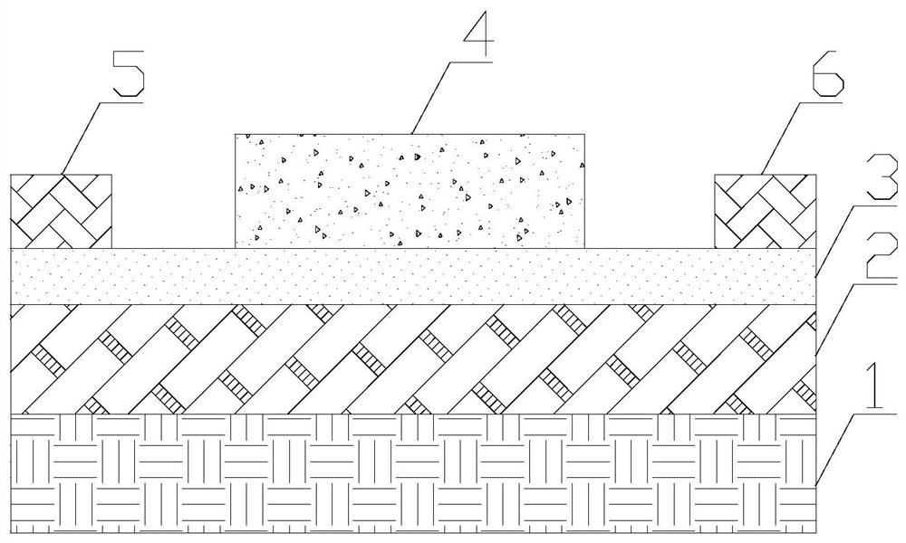
[0020] The invention provides a magnetic tunnel junction micro-tension detector, such as figure 1 As shown, it includes an antiferromagnetic part 1 , a pinning part 2 , a barrier part 3 , a free layer part 4 , a first force applying part 5 and a second force applying part 6 . The material of the antiferromagnetic part 1 is a hard magnetic antiferromagnetic material, specifically, the material of the antiferromagnetic part 1 is IrMn, PtMn, FeMn. The pinning part 2 is placed on the antiferromagnetic part 1 . The material of the pinning part 2 is a metal or semimetal with high spin polarizability, specifically, the material of the pinning part 2 is Co, Fe, CoFe, CoFeB, CoFeAl alloy. The barrier portion 3 is placed on the pinning portion 2 . The material of the barrier portion 3 is aluminum oxide or magnesium oxide. The free layer portion 4 is placed in the middle on the barrier portion 3 . The material of the free layer portion 4 is a soft magnetic material with weak magnetic...

Embodiment 2

[0024] On the basis of Embodiment 1, the first force application part 5 and the second force application part 6 are respectively fixedly connected to opposite side surfaces of the free layer part 4 . That is to say, in addition to the first force applying part 5 and the second force applying part 6 being fixed on the barrier part 3 , the first force applying part 5 and the second force applying part 6 are also fixedly connected to the free layer part 4 . In this way, the micro-tension not only changes the stress in the barrier part 3, but also changes the stress in the free layer part 4, thereby not only changing the quantum tunneling characteristics of the potential barrier part 3, but also changing the stress in the free layer part 4. The internal spin state changes the magnetoresistance of the magnetic tunnel junction more, thereby achieving higher sensitivity micro-pull force detection.

Embodiment 3

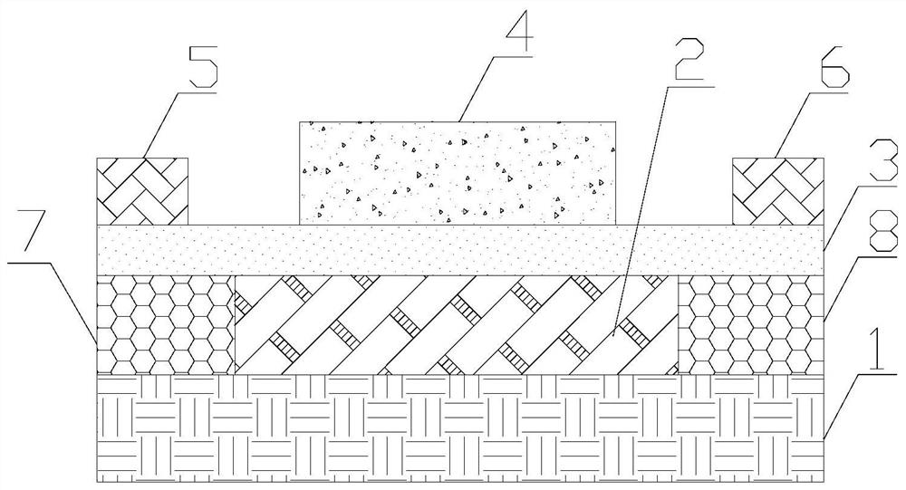
[0026] On the basis of Example 1, such as figure 2 As shown, it also includes a first elastic part 7 and a second elastic part 8, the first elastic part 7 and the second elastic part 8 are arranged on the opposite sides of the pinning part 2 on the antiferromagnetic part 1, and the barrier part 3 is placed On the first elastic part 7, the pinning part 2, and the second elastic part 8, the first force applying part 5 and the second force applying part 6 are respectively fixed on the barrier part 3. The first elastic part 7 and the second elastic part 8 on the upper side. The height of the first elastic part 7 and the second elastic part 8 is the same as that of the pinning part 2 . The first elastic part 7 and the second elastic part 8 are elastic insulating materials. The material of the first elastic part 7 and the second elastic part 8 can be elastic fiber or rubber. In this way, the contact area of ​​the pinning part 2 to the barrier part 3 is reduced, thereby reducing ...


PUM


Abstract

The invention relates to the field of tension detection, and particularly provides a magnetic tunnel junction micro-tension detector; an antiferromagnetic part is made of a hard magnetic antiferromagnetic material, a pinning part is arranged on the antiferromagnetic part, the pinning part is made of metal or semimetal with high spinning polarizability, a barrier part is arranged on the pinning part, a free layer part is arranged in the middle of the barrier part, and a first force application part and a second force application part are fixed to the two ends of the barrier part. In the magnetic tunnel junction micro-tension detector, the pinning part, the barrier part and the free layer part form a magnetic tunnel junction. During application, to-be-measured tension acts on the first force application part and the second force application part, and meanwhile, a magnetic field acts on the detector. The to-be-measured micro-tension is determined by measuring the difference between the magnetoresistance of the magnetic tunnel junction when the micro-tension is applied and when the micro-tension is not applied. The magnetic tunnel junction micro-tension detector has the advantage of high micro-tension detection sensitivity.

Description

technical field [0001] The invention relates to the field of tension detection, in particular to a magnetic tunnel junction micro tension detector. Background technique [0002] Pull force detection belongs to basic physical quantity detection. Pull detection not only has important applications in industrial processes, household appliances, aerospace, automatic control and other fields, but also plays an important role in scientific research on the relationship between material properties and stress under extreme conditions, such as low temperature environments. application. Traditional tension detectors based on capacitance changes or resistance changes have low sensitivity and cannot meet the needs of micro tension detection. Contents of the invention [0003] In order to solve the above problems, the present invention provides a magnetic tunnel junction micro-tension detector, which includes an antiferromagnetic part, a pinning part, a potential barrier part, a free l...

Claims


Application Information

Patent Timeline
IPC IPC(8): G01L1/12
CPCG01L1/12
Inventor 于孟今
Owner 于孟今
Why Eureka
Try Eureka