Optical fiber integrated magnetic tunnel junction photoelectric detector
A technology of photodetector and magnetic tunnel junction, which is applied in the field of photoelectric detection, can solve the problems of low photodetection sensitivity, little influence of conductive characteristics, and inability to meet high technology, and achieve high sensitivity
- Summary
- Abstract
- Description
- Claims
- Application Information
AI Technical Summary
Problems solved by technology
Method used
Image
Examples
Embodiment 1
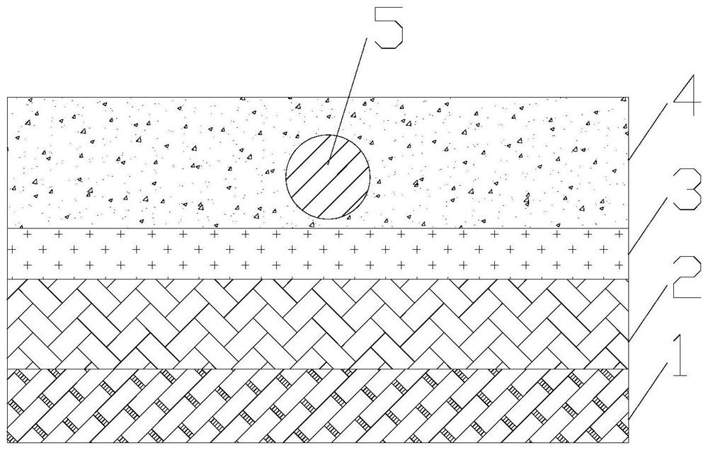
[0024] The invention provides an optical fiber integrated magnetic tunnel junction photodetector, such as figure 1 As shown, it includes an antiferromagnetic layer 1 , a pinning layer 2 , a barrier layer 3 , a free layer 4 , and a fiber core 5 . The material of the antiferromagnetic layer 1 is a hard magnetic antiferromagnetic material, specifically, the material of the antiferromagnetic layer 1 is IrMn, PtMn, FeMn. The pinning layer 2 is placed on the antiferromagnetic layer 1 . The material of the pinning layer 2 is a metal or semi-metal with high spin polarizability, specifically, the material of the pinning layer 2 is Co, Fe, CoFe, CoFeB, CoFeAl alloy. The barrier layer 3 is placed on the pinning layer 2 . The material of the barrier layer 3 is aluminum oxide or magnesium oxide. The free layer 4 is placed on the barrier layer 3 . The material of the free layer 4 is soft magnetic material with weak magnetic anisotropy, specifically, the material of the free layer 4 is N...
Embodiment 2
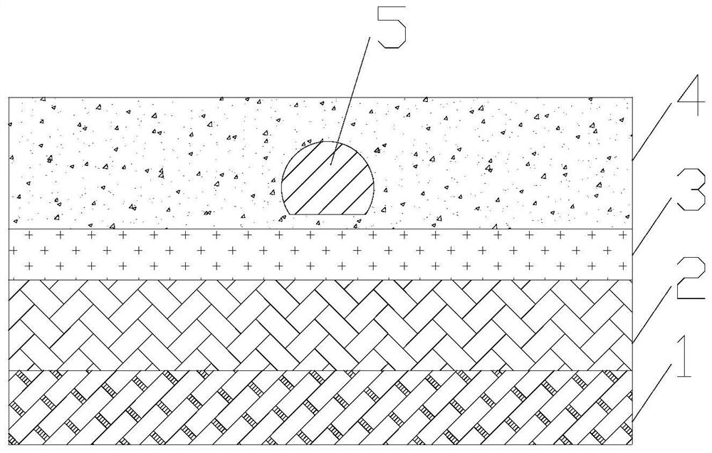
[0027] On the basis of Example 1, such as figure 2 As shown, the side surface of the fiber core 5 is provided with a polishing plane formed by polishing treatment, and the polishing plane is placed on the side of the barrier layer 3 . In this way, the light in the fiber core 5 is more likely to emerge from the polished plane, and the emitted light can change the temperatures of the barrier layer 3 and the free layer 4 more. Further, the polishing plane is parallel to the surface of the barrier layer 3, and the distance between the polishing plane and the barrier layer 3 is less than 100 nanometers, so that the barrier layer 3 is in a stronger light field, so that the barrier layer The temperature of the barrier layer 3 changes more, and the quantum tunneling characteristics of the barrier layer 3 change more, thereby changing the magnetoresistance of the magnetic tunnel junction more, so as to achieve higher sensitivity light detection.
Embodiment 3
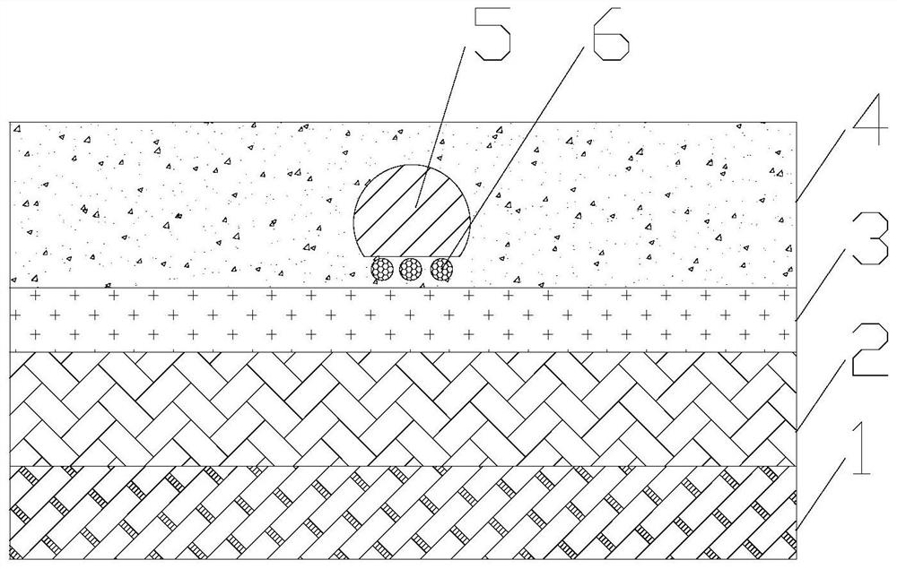
[0029] On the basis of Example 2, such as image 3 As shown, noble metal particles 6 are also included, and the noble metal particles 6 are arranged on the polishing plane. In this way, the light in the fiber core 5 is more easily coupled out of the fiber core 5, and localized surface plasmon resonance is formed on the noble metal particle 6, thereby forming a strong electric field near the noble metal particle 6, thereby changing the potential even more. The temperature of the barrier layer 3 changes more the quantum tunneling characteristics of the potential barrier layer 3, thereby changing the magnetoresistance of the magnetic tunnel junction more, thereby realizing more sensitive light intensity detection. The noble metal particle 6 is circular, and the diameter of the noble metal particle 6 is less than 60 nanometers. In this way, the localized surface plasmon resonance wavelength of the noble metal particle 6 is in the visible light band, because the light propagating i...
PUM
 Abstract
Description
Claims
Application Information
 - R&D
- Intellectual Property
- Life Sciences
- Materials
- Tech Scout
- Unparalleled Data Quality
- Higher Quality Content
- 60% Fewer Hallucinations
Browse by: Latest US Patents, China's latest patents, Technical Efficacy Thesaurus, Application Domain, Technology Topic, Popular Technical Reports.
© 2025 PatSnap. All rights reserved.Legal|Privacy policy|Modern Slavery Act Transparency Statement|Sitemap|About US| Contact US: help@patsnap.com


