Short-time discontinuous direct current grounding fault searching method and system
A DC grounding and fault finding technology, applied in fault location, fault detection by conductor type, short-circuit test, etc., can solve the problem of inability to find short-term intermittent insulation faults, achieve rapid fault troubleshooting and improve stability. Effect
- Summary
- Abstract
- Description
- Claims
- Application Information
AI Technical Summary
Problems solved by technology
Method used
Image

Examples
Embodiment 1
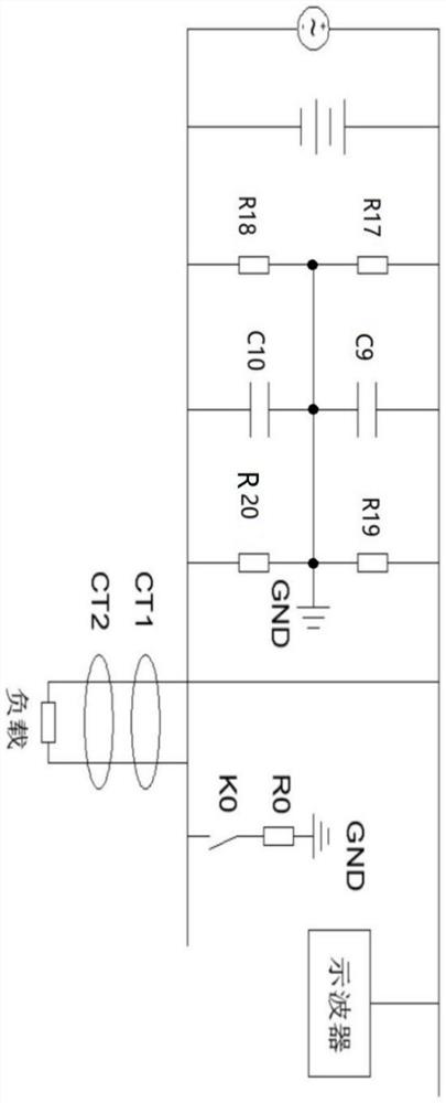
[0031] Such as figure 1 Shown is a DC system analog circuit diagram of a short-term intermittent DC grounding fault finding method, as shown in the figure, the positive DC bus of the DC power supply is connected to one end of the resistor R17, one end of the resistor R19 and one end of the capacitor C9, and the negative DC The bus bar is connected to one end of the resistor R18, one end of the resistor R20, and one end of the capacitor C10, the other end of the resistor R17, the other end of the resistor R18, the other end of the resistor R19, the other end of the resistor R20, the other end of the capacitor C9 and the capacitor C10 The other end of the resistor is grounded; the resistor R17 is equal to the resistance of the resistor R18, indicating the positive and negative insulation resistance of the DC system; the capacitor C9 is equal to the capacitor C10, indicating the ground capacitance of the DC system; the resistance of the resistor R19 and the resistor R20 are equal ...
Embodiment 2
[0044] Such as Figure 4 A schematic structural diagram of a short-time discontinuous DC grounding fault finding system is shown. The system includes a search host, several current characteristic waveform acquisition modules, several clamp transformers CT and several user terminals. In this example, the clamp The transformer CT adopts a highly integrated clamp current transformer, and the user end adopts a mobile phone end. The current characteristic waveform acquisition module is connected to several clamp transformers CT, and the search host is respectively connected to several user terminals and several current characteristic waveform acquisition modules.
[0045] In the specific implementation, the connection between the clamp transformer CT and the current characteristic waveform acquisition module described in this implementation adopts a wired connection, and the connection between the search host and the user terminal and the current characteristic waveform acquisition...
Embodiment 3
[0050] Such as Figure 5 It is a DC bus voltage sampling circuit diagram, the DC bus voltage sampling circuit includes an input module, a negative feedback module and an output module, and the negative feedback module is connected to the input module and the output module respectively.
[0051] The input module includes a resistor R1, a resistor R2, a resistor R3, a diode D3 and an optocoupler OPT1, one end of the resistor R1 is respectively connected to the cathode of the diode D3 and the positive emitter of the optocoupler OPT1, and one end of the resistor R2 is respectively connected to the positive pole of the emitter of the optocoupler OPT1. The anode of the diode D3 is connected to the emitter cathode of the optocoupler OPT1, the receiving end C of the optocoupler OPT1 is connected to the power supply, and the receiving end E of the optocoupler OPT1 is connected to one end of the resistor R3 as the output terminal of the input module It is connected to the negative feedb...
PUM
 Abstract
Description
Claims
Application Information
 - R&D
- Intellectual Property
- Life Sciences
- Materials
- Tech Scout
- Unparalleled Data Quality
- Higher Quality Content
- 60% Fewer Hallucinations
Browse by: Latest US Patents, China's latest patents, Technical Efficacy Thesaurus, Application Domain, Technology Topic, Popular Technical Reports.
© 2025 PatSnap. All rights reserved.Legal|Privacy policy|Modern Slavery Act Transparency Statement|Sitemap|About US| Contact US: help@patsnap.com