Cleaning robot control method and device and terminal equipment

A cleaning robot and control method technology, applied in non-electric variable control, control/regulation system, two-dimensional position/channel control, etc., can solve the problem of inconsistent tilting state of photovoltaic modules, control system, sensor failure, falling, etc. problems, to avoid operational risks, ensure safe passage, and achieve the effect of collaborative control

Pending Publication Date: 2021-12-10
仁洁智能科技有限公司
View PDF0 Cites 1 Cited by
  • Summary
  • Abstract
  • Description
  • Claims
  • Application Information

AI Technical Summary

Problems solved by technology

[0003] At present, cleaning robots are generally used in power stations for cleaning photovoltaic modules, and in order to improve the efficiency of robots, multiple modules in the same row are connected in series. The module string corresponds to a flat single axis, and the same row of modules has multiple flat single axes. During the horizontal single-axis rotation of the bracket, the control system, sensors, etc. may fail, resulting in inconsistent angles or heights of different horizontal single-axis rotations in the same row, which further makes the tilting state of the photovoltaic modules on it inconsistent. , the large angle difference between the photovoltaic modules will make the robot unable to pass through, or even fall down
At present, the robot operation technology is based on the individual robot, and does not consider the safety of the robot when it is running.

Method used


Image

  • Cleaning robot control method and device and terminal equipment
  • Cleaning robot control method and device and terminal equipment
  • Cleaning robot control method and device and terminal equipment

Examples


Embodiment 1

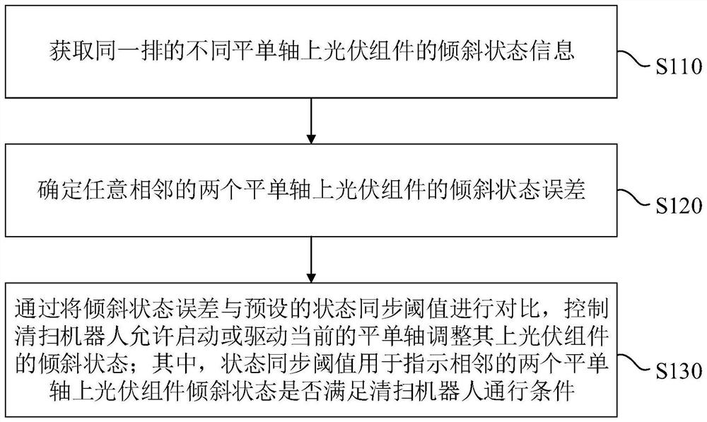
[0033] figure 1 It is a schematic flow chart of a cleaning robot control method provided in Embodiment 1 of the present invention. This method is applicable to the situation of the flat single-axis linkage control between the cleaning robot and the photovoltaic flat single-axis tracking system. This method can be controlled by the cleaning robot control device. Execution, wherein the device can be realized by software and / or hardware, and generally integrated on the terminal equipment. In this embodiment, the terminal equipment includes but not limited to computers, servers, management platforms, etc.

[0034] like figure 1 As shown, a cleaning robot control method provided in Embodiment 1 of the present invention includes the following steps:

[0035] S110. Obtain tilt state information of photovoltaic modules on different flat single axes in the same row.

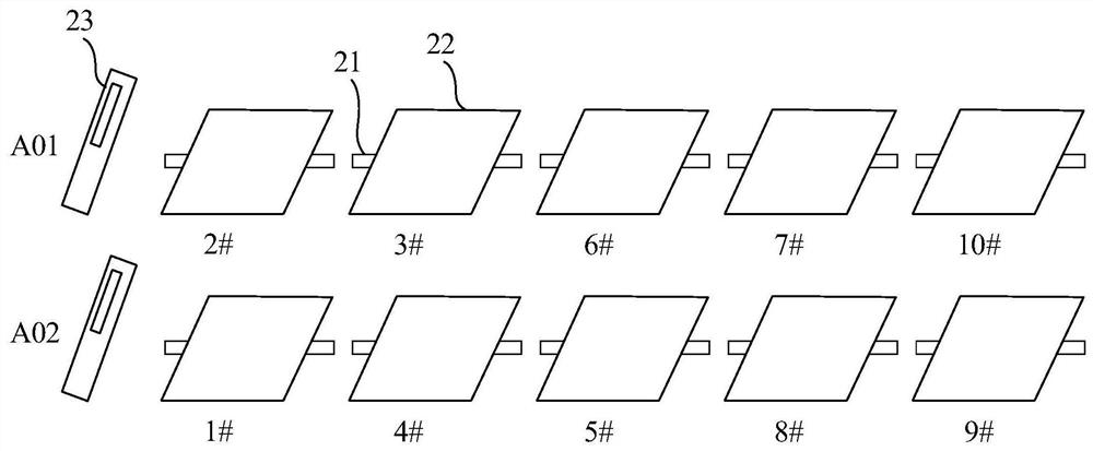
[0036] figure 2 It is a schematic diagram of the arrangement of photovoltaic modules provided by the embodiment of ...

Embodiment 2

[0055] Figure 4 It is a schematic flow chart of a cleaning robot control method provided by Embodiment 2 of the present invention. This Embodiment 2 is optimized on the basis of the foregoing embodiments. In this embodiment, the acquisition of tilt state information of photovoltaic modules on different flat uniaxial axes in the same row is further embodied as: S210, acquiring rotation angle information of different flat uniaxial axes in the same row.

[0056] Further, this embodiment will also determine the tilt state error of any two adjacent flat single-axis photovoltaic modules, which is further embodied as: S220, calculate the rotation angle error of any two adjacent flat single-axis photovoltaic modules . In addition, by comparing the tilt state error with the preset state synchronization threshold, the cleaning robot is controlled to allow starting or driving the current flat single axis to adjust the tilt state of the photovoltaic module on it, which is further embodi...

Embodiment 3

[0068] Figure 6 It is a schematic flow chart of a cleaning robot control method provided by Embodiment 3 of the present invention. This Embodiment 3 is optimized on the basis of the foregoing embodiments. In this embodiment, the acquisition of tilt state information of photovoltaic modules on different flat single axes in the same row is further embodied as: 310. Obtain height information of preset end portions of photovoltaic modules on different flat single axes in the same row.

[0069]Furthermore, this embodiment will also determine the tilt state error of any two adjacent flat uniaxial photovoltaic modules, which is further embodied as: S320. Calculate the preset end of any two adjacent flat uniaxial photovoltaic modules height difference.

[0070] In addition, by comparing the tilt state error with the preset state synchronization threshold, the cleaning robot is controlled to allow starting or driving the current flat single-axis to adjust the tilt state of the photov...


PUM


Abstract

The invention discloses a cleaning robot control method and device and terminal equipment. The control method comprises the following steps: acquiring inclination state information of photovoltaic modules on different flat single axes in the same row; determining the inclination state error of the photovoltaic modules on any two adjacent flat single shafts; comparing the inclination state error with a preset state synchronization threshold value, and controlling the cleaning robot to be allowed to start or drive the current flat single axes to adjust the inclination state of the photovoltaic module on the flat single axes; wherein the state synchronization threshold value is used for indicating whether the inclination state of the photovoltaic modules on the two adjacent flat single axes meets the passing condition of the cleaning robot or not. By means of the method, the problem that the cleaning robot cannot normally pass through the photovoltaic modules due to rotation errors or faults of the flat single axes can be solved, the operation risk is effectively recognized, it is guaranteed that the cleaning robot normally passes through the photovoltaic modules, and meanwhile the risk that the cleaning robot falls off from the photovoltaic modules is avoided.

Description

technical field [0001] The embodiments of the present invention relate to the field of photovoltaic technology, and in particular to a cleaning robot control method, device and terminal equipment. Background technique [0002] In photovoltaic power stations, in order to improve power generation efficiency, many use flat single-axis tracking brackets. The photovoltaic modules are assembled on the flat single-axis tracking brackets. The flat single-axis brackets will rotate at regular intervals to adjust the inclination of photovoltaic modules to ensure Photoelectric conversion efficiency of photovoltaic modules. In addition, because the photovoltaic module is outdoors, the dust on it will affect the photoelectric conversion efficiency, so it is also very important to ensure the cleanliness of the photovoltaic module. [0003] At present, cleaning robots are generally used in power stations for cleaning photovoltaic modules, and in order to improve the efficiency of robots, m...

Claims


Application Information

Patent Timeline
IPC IPC(8): G05D1/02
CPCG05D1/0242G05D1/0259G05D1/0214G05D1/028G05D1/0276Y02E10/50
Inventor 不公告发明人
Owner 仁洁智能科技有限公司
Why Eureka
Try Eureka