Hand controller for electric lifting table and electric lifting table
A lifting table, electric technology, applied in the table, table, circuit and other directions that can change the height of the table, can solve the problems of increasing the manufacturing cost and the size of the hand controller, and achieve the effect of convenient operation and strong operation interest.
- Summary
- Abstract
- Description
- Claims
- Application Information
AI Technical Summary
Problems solved by technology
Method used
Image
Examples
Embodiment 1
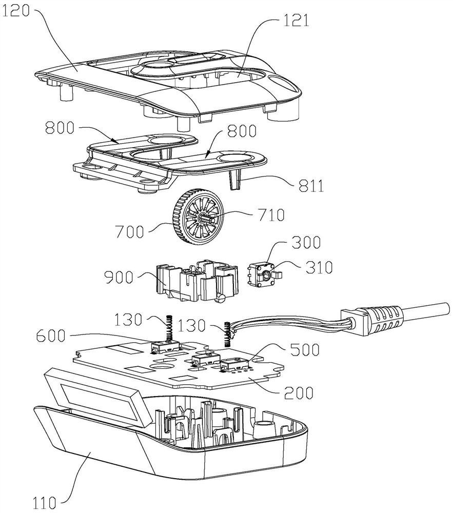
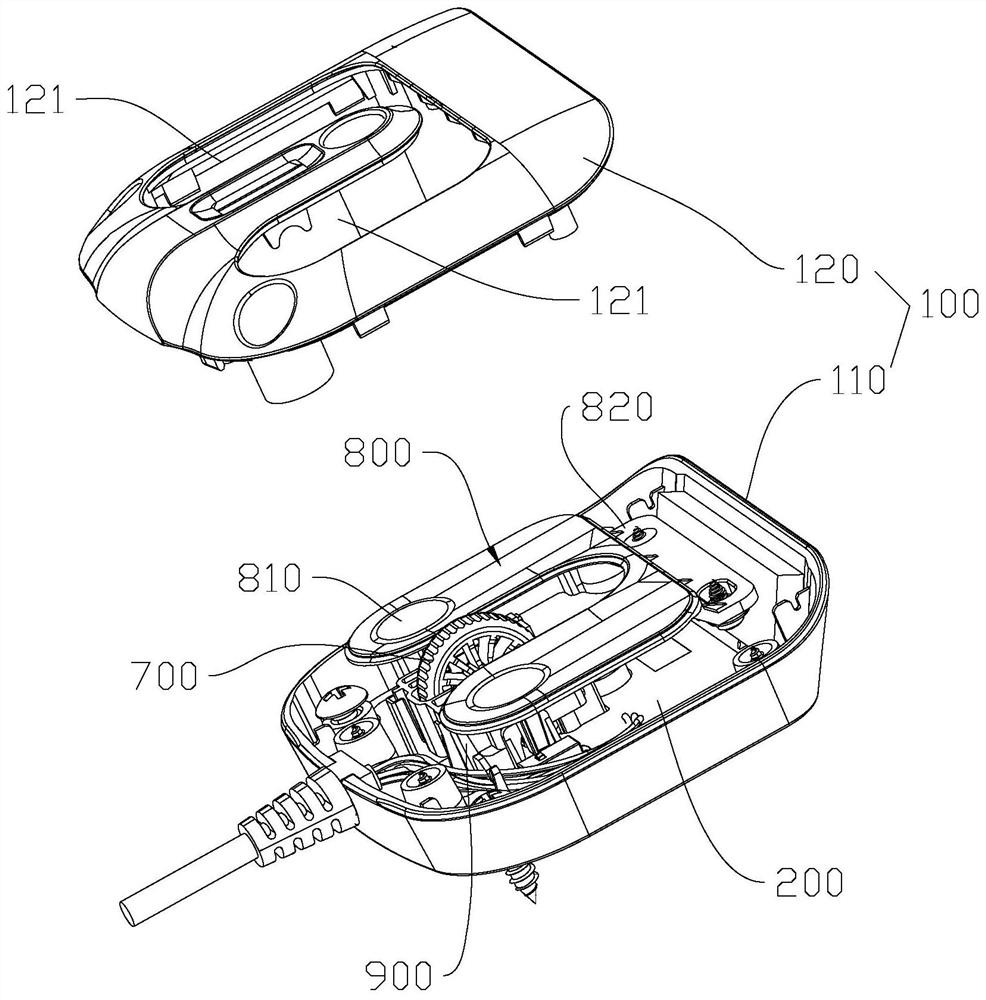
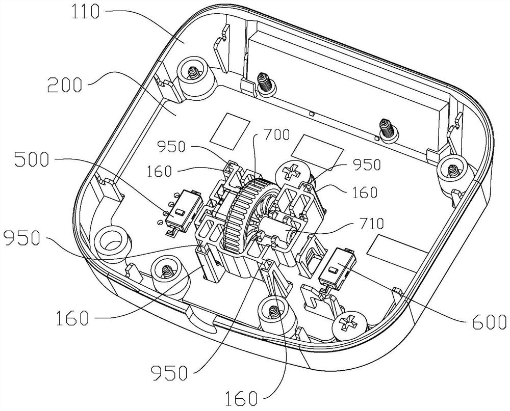
[0060] refer to Figure 1 to Figure 8 As shown, the hand controller for electric lifting table in this embodiment includes a housing 100 and a main control board 200, the housing 100 includes a base 110 and a cover 120, the main control board 200 is arranged in the housing 100 and fixed on the base 110, the casing 100 in this embodiment runs through a partially exposed roller 700 that is used to control the lifting of the electric lift table, that is, the roller 700 is installed through the cover 120, and the main control board 200 is connected to the rotation angle conversion of the roller 700. An encoder that generates electrical signals, and the main control board 200 controls the lifting of the electric lifting table according to the electrical signals. In this way, when using the hand controller, the lifting control of the electric lifting table can be realized by rolling the roller 700 in the forward and reverse directions, thereby saving the setting of the up button and...
Embodiment 2
[0077] Such as Figure 9 to Figure 10 As shown, compared with Embodiment 1, the difference of this embodiment is that the rotary encoder 300 is welded and fixed on the main control board 200, one end of the rotating shaft 710 is connected with the input sleeve 310 and rotates synchronously, and the other end is correspondingly provided with a switch 210, the rotating shaft 710 in this embodiment has a certain degree of elasticity, so as to realize the elastic installation of the roller 700, so that after pressing the roller 700, the other end of the rotating shaft 710 can deform and move and trigger the setting switch 210, canceling the pressing of the roller 700 Finally, the rotating shaft 710 resets under its own elasticity and drives the roller 700 to reset, and the overall structure is relatively simple.
[0078] In order to horizontally limit the other end of the rotating shaft 710 to prevent the rotating shaft 710 from breaking due to excessive force when rolling the rol...
Embodiment 3
[0080] Such as Figure 11 to Figure 12 As shown, compared with Embodiment 1 and Embodiment 2, the difference of this embodiment is that the encoder is a grating encoder 400, and the grating encoder 400 includes an infrared transmitter 410 and an infrared receiver 420 arranged oppositely, and the base 110 is also provided with a second bracket that runs through the main control board 200. The second bracket includes a fixed frame and a floating frame 1100. The fixed frame and the floating frame 1100 are arranged oppositely. 210 is set corresponding to the boss 1101, and the fixed frame includes two fixed pillars 1200 arranged at intervals, the infrared receiver 420 is located between the two fixed pillars 1200, one end of the rotating shaft 710 is sleeved with a torsion spring 1300, and the two ends of the torsion spring 1300 are respectively The hook is supported on two fixed pillars 1200, and one end of the rotating shaft 710 is rotatably matched with the mounting hole on the...
PUM
 Abstract
Description
Claims
Application Information
 - R&D
- Intellectual Property
- Life Sciences
- Materials
- Tech Scout
- Unparalleled Data Quality
- Higher Quality Content
- 60% Fewer Hallucinations
Browse by: Latest US Patents, China's latest patents, Technical Efficacy Thesaurus, Application Domain, Technology Topic, Popular Technical Reports.
© 2025 PatSnap. All rights reserved.Legal|Privacy policy|Modern Slavery Act Transparency Statement|Sitemap|About US| Contact US: help@patsnap.com


