A wire stripping machine for cables

A wire stripping machine and cable technology, used in cable installation, cable installation devices, equipment for dismantling/armored cables, etc., can solve the problems of internal wire core damage, hand injury, wasting time, etc., to ensure accurate cutting performance, reduce friction, collect complete effects

Active Publication Date: 2022-02-15
常州市生生线缆有限公司
View PDF4 Cites 0 Cited by
  • Summary
  • Abstract
  • Description
  • Claims
  • Application Information

AI Technical Summary

Problems solved by technology

When working on cables, it is necessary to peel off the outer sheath of the connection end, usually manually using pliers to handle one by one, but in some cases, it is necessary to handle multiple cables at the same time, and at this time, a single cable is stripped In addition, the commonly used tool for cable stripping operations is scissors, which is time-consuming and labor-intensive to use, and it will also cause multiple stripping operations on a cable due to uneven cutting, which is easy to cause injury to the opponent.
And the notch is too big and too deep will often cause damage to the internal wire or inner core
[0003] In the prior art, when the machine is used to strip the wire, only the insulation layer can be stripped off, and the cable cannot be cut at the same time. When the layer falls off, it has a large inertia, so it is easy to fly out when the insulating layer falls off, and it is troublesome to collect the insulating layer

Method used


Image

  • A wire stripping machine for cables
  • A wire stripping machine for cables
  • A wire stripping machine for cables

Examples


Embodiment Construction

[0036] The present invention is described in further detail now in conjunction with accompanying drawing. These drawings are all simplified schematic diagrams, which only illustrate the basic structure of the present invention in a schematic manner, so they only show the configurations related to the present invention.

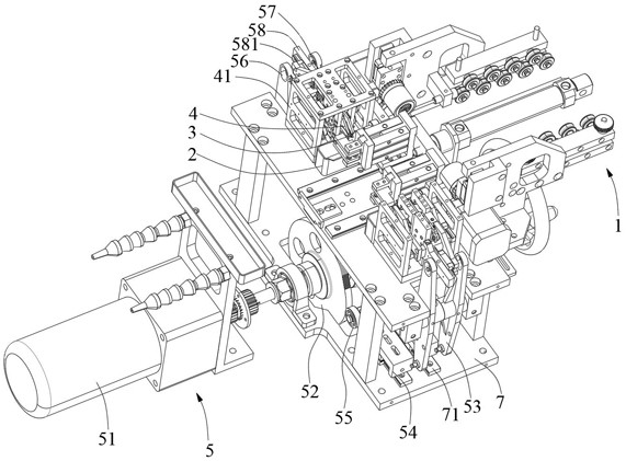
[0037] Such as Figure 1 to Figure 7 As shown, this embodiment provides a wire stripping machine for cables, including: a conveying mechanism 1, the conveying mechanism 1 is used for conveying cables, and through the setting of the conveying mechanism 1, it can straighten the transportation of cables, so that For peeling the cable, avoiding the situation that the cable is bent or bent to affect the peeling; the waste box 2, the waste box 2 is located below the output end of the conveying mechanism 1, and is used to hold the waste that falls on the cable, Such as the cut cable and the insulating layer stripped from the cable; the slitting mechanism 3, the slit...


PUM


Abstract

The invention relates to the technical field of cables, in particular to a wire stripping machine for cables, comprising: a waste box, the waste box is located below the output end of the conveying mechanism; a slitting mechanism, the slitting mechanism is installed at the output end of the conveying mechanism, and The cutting mechanism is used to cut the cable; the stripping mechanism is used to cut off the insulation layer of the cut cable end and separate it from the cable; the driving mechanism is used to drive the slitting mechanism and the stripping mechanism to work simultaneously; the cross-cutting mechanism , the cross-cutting mechanism is in an inverted "U" shape, and the two ends of the cross-cutting mechanism pass through the two side walls of the cutting position of the stripping mechanism, and the heights of the two ends of the cross-cutting mechanism are different; the cross-cutting mechanism follows the stripping mechanism to cut off the cable end When removing the insulation layer of the head, one end of the cross-cutting mechanism retracts to the inside of the stripping mechanism, and the other end of the cross-cutting mechanism is inserted into the insulation layer of the cable; when the stripping mechanism is separated from the cable, the retracted end of the cross-cutting mechanism rebounds to push Drop and insert the insulation at the other end of the crosscutting mechanism.

Description

technical field [0001] The invention relates to the technical field of cables, in particular to a wire stripping machine for cables. Background technique [0002] Cable is a kind of electric energy or signal transmission device, including power cable, control cable, compensation cable, shielded cable, high temperature cable, computer cable, signal cable, coaxial cable and fire-resistant cable, etc. They are all composed of single or multi-strand wires and insulation layers, and are used to connect circuits, electrical appliances, etc. When working on cables, it is necessary to peel off the outer sheath of the connection end, usually manually using pliers to handle one by one, but in some cases, it is necessary to handle multiple cables at the same time, and at this time, a single cable is stripped In addition, scissors are often used for cable stripping operations. Using scissors is time-consuming and labor-intensive, and the uneven cutting will cause multiple stripping ope...

Claims


Application Information

Patent Timeline
Patent Type & Authority Patents(China)
IPC IPC(8): H02G1/12
CPCH02G1/1263H02G1/127H02G1/005
Inventor 施强强
Owner 常州市生生线缆有限公司
Why Eureka
Try Eureka