

Portable medical equipment maintenance device control circuit
A technology for controlling circuits and medical equipment, applied in the field of medical equipment, can solve problems such as easy failure, easy aging, delay in patient treatment, etc., and achieve the effect of convenient maintenance and avoiding discomfort
- Summary
- Abstract
- Description
- Claims
- Application Information
AI Technical Summary
Problems solved by technology
Method used
Image

Examples
Embodiment 1
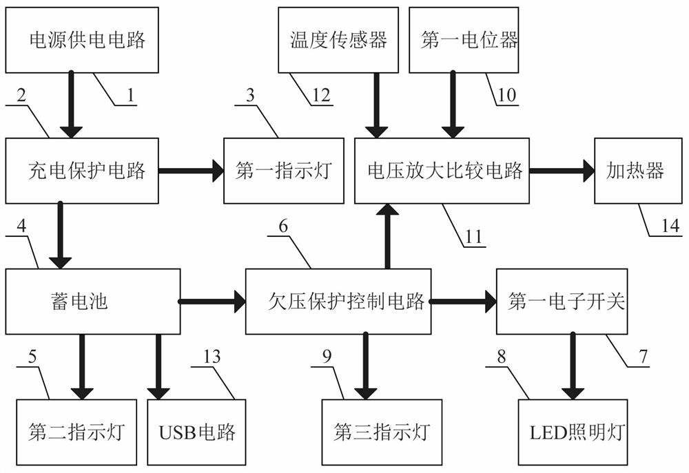
[0024] A portable medical equipment maintenance device control circuit, such as figure 1As shown, it includes a power supply circuit 1, a charging protection circuit 2, a first indicator light 3, a battery 4, a second indicator light 5, an undervoltage protection control circuit 6, a third indicator light 9 and a USB circuit 13. The charging The output end of the protection circuit 2 is connected to the first indicator light 3, the output end of the charging protection circuit 2 is connected to the battery 4, the battery 4 is connected to the second indicator light 5, and the input end of the USB circuit 13 is connected to the battery 4 is connected, the battery 4 is connected to the input end of the undervoltage protection control circuit 6, the output end of the undervoltage protection control circuit 6 is connected to the third indicator light 9, and the power supply circuit 1 is the charging protection circuit 2 and The first indicator light 3 supplies power, and the batte...
Embodiment 2
[0027] On the basis of Example 1, as figure 1 As shown, it also includes a first electronic switch 7 and an LED lighting lamp 8, the output end of the undervoltage protection control circuit 6 is connected to the first electronic switch 7, and the first electronic switch 7 is connected to the LED lighting lamp 8, The battery 4 supplies power to the first electronic switch 7 and the LED lighting lamp 8 .
[0028] The medical staff short presses the first electronic switch 7, the LED lighting 8 starts to work, the LED lighting 8 lights up, provides illumination, and facilitates the medical staff to maintain the medical equipment, and long press the first electronic switch 7, the LED lighting 8 is turned off.
[0029] It also includes a first potentiometer 10, a voltage amplification and comparison circuit 11, a temperature sensor 12 and a heater 14. The output end of the under-voltage protection control circuit 6 is connected to the input end of the voltage amplification and com...
Embodiment 3
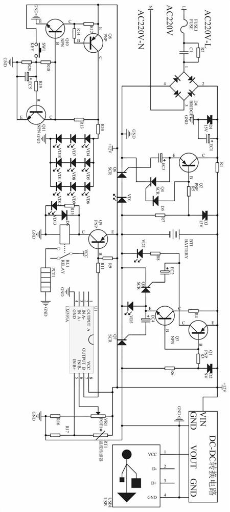
[0032] A portable medical equipment maintenance device control circuit, such as figure 2 As shown, the charging protection circuit 2 includes a fuse FUSE1, a rectifier bridge D4, a resistor R1, a resistor R2, a resistor R5, a resistor R7, a capacitor C1, a diode D1, a diode D3, a diode D5, a light-emitting diode VD1, a battery BT1, a triode Q2, electrolytic capacitor EC1, electrolytic capacitor EC3, thyristor Q4 and thyristor Q6, the 4th pin of the rectifier bridge D4 is grounded, the 3rd pin of the rectifier bridge D4 is connected to the AC N terminal, the 1st pin of the rectifier bridge D4 The other end of the fuse FUSE1 is connected to the AC terminal L, the 2-pin series diode D1 of the rectifier bridge D4 is grounded, the 2-pin series electrolytic capacitor EC1 of the rectifier bridge D4 is grounded, and the rectifier bridge D4 is connected to the ground. Pin 2 of the bridge D4 is connected to one end of the resistor R1, the other end of the resistor R1 is connected to +1...
PUM
 Abstract
Description
Claims
Application Information