
Small low-flow-resistance swirl nozzle

A spray nozzle, low flow resistance technology, applied in the direction of spray device, spray device, etc., can solve the problems of difficulty in cleaning and maintenance of the nozzle, increase the total power consumption of the system, and reduce the spray quality, so as to optimize the system structure design and reduce the pump power. , the effect of easy operation

Pending Publication Date: 2021-12-14
UNIV OF SCI & TECH OF CHINA
View PDF0 Cites 0 Cited by
  • Summary
  • Abstract
  • Description
  • Claims
  • Application Information

AI Technical Summary

Problems solved by technology

The nozzle has a fixed spray flow-pressure curve according to its own design. In order to achieve the spray flow required by a single nozzle, it is necessary to increase the spray pump power and increase the nozzle pressure. If the selected nozzle has a lower flow rate under the same pressure, it will increase the system. Total power consumption; nozzles are easily blocked by impurities in the supply liquid during long-term work, resulting in problems such as reduced spray quality and flow reduction, which require maintenance or renewal. Difficult to clean up and maintain

Method used


Image

  • Small low-flow-resistance swirl nozzle
  • Small low-flow-resistance swirl nozzle
  • Small low-flow-resistance swirl nozzle

Examples


Embodiment Construction

[0026] The present invention will be further described through the embodiments below in conjunction with the accompanying drawings.

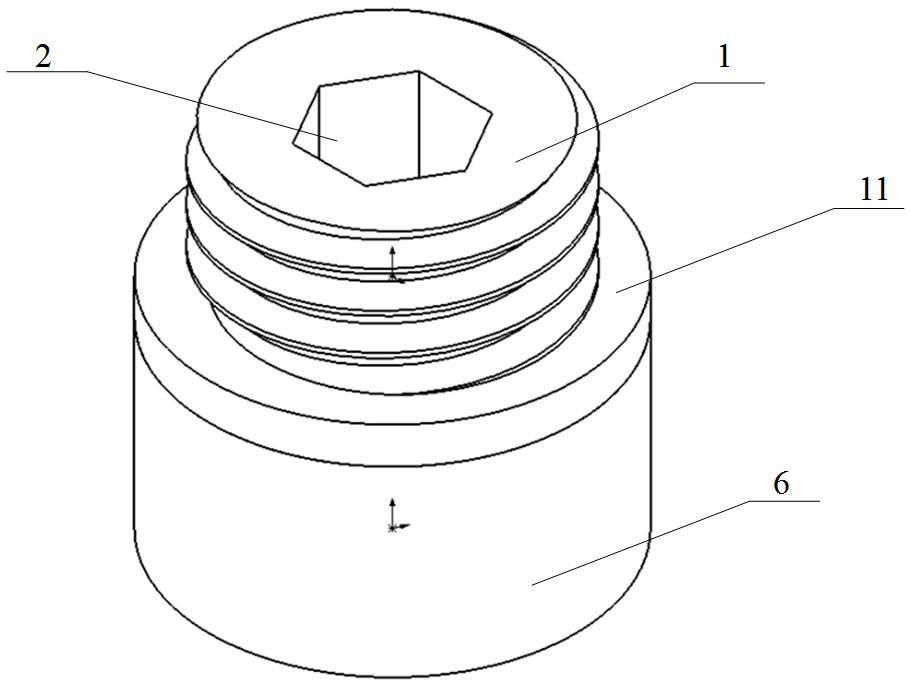
[0027] see figure 1 , a small swirl spray nozzle with low flow resistance includes a swirl joint 1 and a nozzle housing 6, which are coaxially fixedly connected by threads.

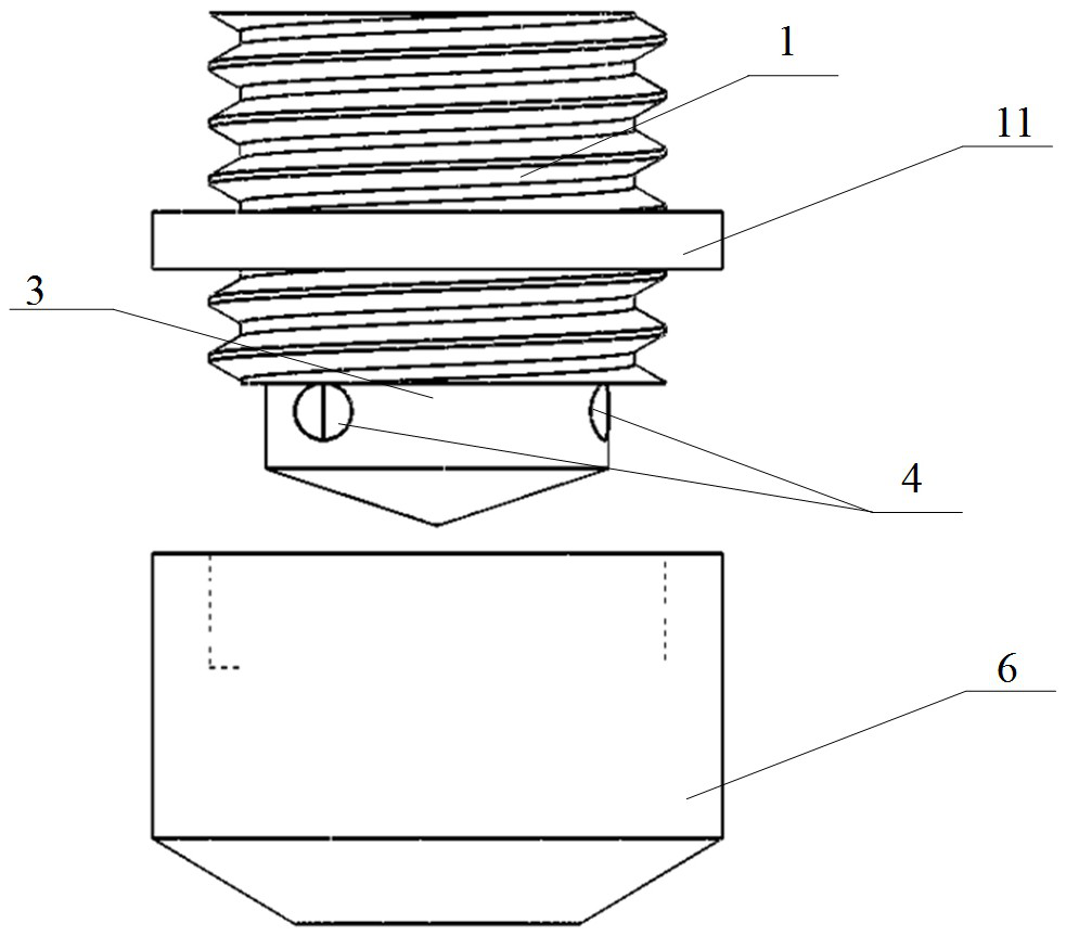
[0028] see figure 2 , The cyclone joint 1 is a screw rod, one axial end is a conical end 12, and the other axial end is provided with a hexagonal liquid inlet hole 2; the side length of the hexagon is 2 mm. The hole wall of the liquid inlet hole 2 adjacent to the conical end 12 is evenly distributed with three guide channels 4 through the hole wall, see Figure 4 . The diameter of the flow guide 4 is 1 mm, the distance h between the axis of the liquid inlet 2 and the axis of the flow guide 4 is 2 mm, and the ratio of the distance h to the diameter of the flow guide 4 is 2.0. The cyclone joint 1 where the outlets of the three flow guides 4 are located is cylindrical, an...


PUM

PropertyMeasurementUnit
Axial heightaaaaaaaaaa
Diameteraaaaaaaaaa

Abstract

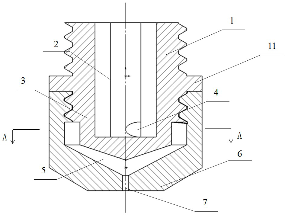
The invention relates to a small low-flow-resistance swirl nozzle, and belongs to the technical field of pressure swirl nozzles. The small low-flow-resistance swirl nozzle comprises a swirler connector and a nozzle shell, wherein one axial end of the swirler connector is a conical end, and a hexagonal liquid inlet hole is formed in the other axial end of the swirler connector; more than two flow guide channels are uniformly formed in the hole wall of the liquid inlet hole; a spraying hole is formed in the axial center of the closed end of the nozzle shell; an inner cone frustum is arranged in the nozzle shell; a funnel-shaped swirl cavity is formed between the conical end of the swirler connector and the inner cone frustum of the nozzle shell; outlets of more than two flow guide channels on the swirler connector are positioned in the swirl cavity; and during working, fluid enters from the liquid inlet hole, enters the swirl cavity through the flow guide channels, forms swirl in the swirl cavity and then is sprayed out through the spraying hole. The flow resistance of an internal flow channel of the swirl nozzle is small, and a spray cone angle of 35-45 degrees can be obtained under the spray head pressure of 1.5 bar; and the spray flow not less than 10 L / h can be obtained under the pressure of 2 bar, so that the pump power required by the system can be reduced.

Description

technical field [0001] The invention belongs to the technical field of pressure swirl nozzles, in particular to a small pressure swirl spray nozzle with low flow resistance. Background technique [0002] Spray nozzles play a key role in a variety of engineering applications, among which the pressure swirl nozzle has a good spray angle, excellent atomization quality, a single nozzle can effectively cover a large area, and has a good performance in liquid spray atomization application. [0003] In the actual application of nozzles, many problems will be faced. The nozzle has a fixed spray flow-pressure curve according to its own design. In order to achieve the spray flow required by a single nozzle, it is necessary to increase the spray pump power and increase the nozzle pressure. If the selected nozzle has a lower flow rate under the same pressure, it will increase the system. Total power consumption; nozzles are easily blocked by impurities in the supply liquid during long...

Claims


Application Information

Patent Timeline
IPC IPC(8): B05B1/02
CPCB05B1/02
Inventor 程文龙赵锐郑磊付豪潘宇晖陈健
Owner UNIV OF SCI & TECH OF CHINA
Learn More