Aerial image geometric correction method based on attitude information of unmanned aerial vehicle

A geometric correction and aerial image technology, applied in the field of image processing, can solve problems such as blank or repeated pixels, difficulty in interpolating pixel values, lack of pixels, etc., and achieve the effect of avoiding correction errors

Pending Publication Date: 2021-12-14
HANGZHOU DIANZI UNIV
View PDF0 Cites 5 Cited by
  • Summary
  • Abstract
  • Description
  • Claims
  • Application Information

AI Technical Summary

Problems solved by technology

The essence of image correction is to realize the geometric transformation between two two-dimensional images. Therefore, before image correction, the geometric relationship between the original image and the corrected image must be established. Two methods are usually used, namely direct method and indirect method. Correction, Li Zheng proposed a method of image geometric correction using only aerial flight information (Li Zheng, "Research on Geometric Correction Technology for UAV Remote Sensing Images Lacking Control Points", University of Electronic Science and Technology of China, 2010), which is Through the direct method, according to the image plane coordinates of each image point on the original image and the geometric relationship established by the attitude information, the image plane coordinates of the corresponding image points on the corrected image are solved one by one, but the image plane coordinates of the corrected image by this method If the points are arranged irregularly, there may be blank or repeated pixels, which will cause a certain degree of difficulty to the interpolation of pixel values, so it is difficult to obtain a corrected image with regular arrangement of pixels

Method used


Image

  • Aerial image geometric correction method based on attitude information of unmanned aerial vehicle
  • Aerial image geometric correction method based on attitude information of unmanned aerial vehicle
  • Aerial image geometric correction method based on attitude information of unmanned aerial vehicle

Examples


Embodiment Construction

[0037] In order to make the object, technical solution and advantages of the present invention clearer, the present invention will be described in detail below in combination with specific embodiments and accompanying drawings, and the specific embodiments are described to simplify the present invention. However, it should be recognized that the present invention is not limited to the illustrated embodiments, and that various modifications of the present invention are possible without departing from the basic principles, and that these equivalent forms also fall within the scope of the appended claims of this application. limited range.

[0038] Such as figure 1 and figure 2 As shown, a geometric correction method based on UAV aerial image attitude information, the specific implementation is as follows:

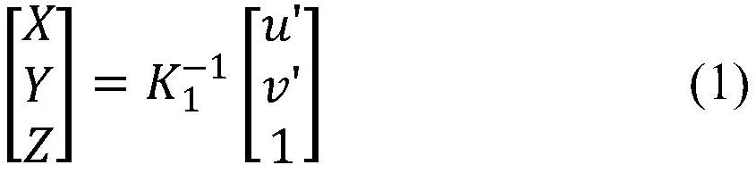
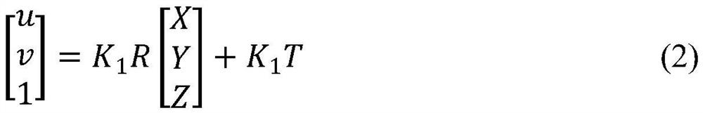
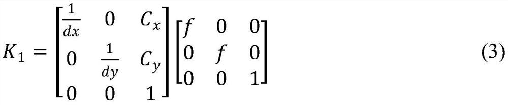
[0039] Step 1: Find the physical equivalent coordinates corresponding to the corrected image coordinates

[0040] Calculate the physical length of the unit pixel accordin...


PUM


Abstract

The invention discloses an aerial image geometric correction method based on attitude information of an unmanned aerial vehicle. The method is characterized in that image interior orientation elements of aerial images are utilized, POS parameters of the aerial images are directly used as image exterior orientation elements, and geometric correction of preprocessed unmanned aerial vehicle remote sensing images is achieved through three-dimensional reconstruction space coordinate conversion and indirect method image correction. According to the method, pixel information of original images are fully utilized, multiple attitude parameters participate in correction at the same time, and correction errors caused by the fact that multiple parameters do not participate in correction smoothly in a traditional method in the prior art are avoided; when manual control point pair selection cannot be carried out, geometric correction is carried out on the aerial images of the unmanned aerial vehicle, so as to enable the images to better meet standards; corrected images with regularly arranged image points are obtained, so that subsequent aerial image registration, splicing, and other processing are facilitated.

Description

technical field [0001] The invention relates to the field of image processing, in particular to an aerial image geometric correction method based on attitude information of an unmanned aerial vehicle. Background technique [0002] With the rapid development of UAVs, UAV low-altitude remote sensing technology has gradually become an important means of obtaining spatial information. By using a specific processing system, a series of operations are performed on the pixels in the aerial image of the UAV, and the purpose of information processing and information extraction is finally achieved. So far, UAVs have been well applied in various projects such as building surveying, fault detection, and wind power inspection. [0003] However, during the aerial photography mission of the UAV, its flight movement may be affected by some external factors such as wind and airflow, which may change the attitude of the UAV imaging sensor, and the UAV shooting platform may appear pitch, The...

Claims


Application Information

Patent Timeline
Patent Type & Authority Applications(China)
IPC IPC(8): G06T5/00G06T3/40G06T7/80
CPCG06T5/006G06T3/4007G06T7/80G06T2207/10032
Inventor 赵辽英向罗巧
Owner HANGZHOU DIANZI UNIV
Why Eureka
Try Eureka