Circulating heat preservation granary for brown rice or rice

A technology for granary and brown rice, which is applied to fruit hanging devices, botanical equipment and methods, gardening, etc., can solve the problems of uneven distribution of cooling effect, poor cooling effect of grain, and inability to achieve optimal cooling effect, so as to achieve cooling effect. Good effect, low energy consumption, uniform cooling effect

Pending Publication Date: 2021-12-17
TAIZHOU YIMING MASCH CO LTD
View PDF6 Cites 0 Cited by
  • Summary
  • Abstract
  • Description
  • Claims
  • Application Information

AI Technical Summary

Problems solved by technology

[0004] However, the cooling effect of this structure on the granary is unevenly distributed, and the closer to the wall of the granary, the better the cooling eff

Method used


Image

  • Circulating heat preservation granary for brown rice or rice
  • Circulating heat preservation granary for brown rice or rice
  • Circulating heat preservation granary for brown rice or rice

Examples


Example Embodiment

[0032] Example 1:

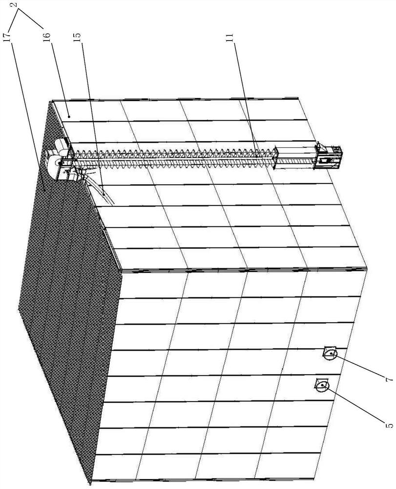
[0033] One kind or brown rice granary incubation cycle, comprising a body 1 with a barn, granary located outer periphery of the main body 1 are set insulation housing 2, 3 is formed, the outer housing 2 with a thermal insulating space between the housing 2 and an insulation body granary is provided with a cold air outlet end of the drum 4, the cold drum 4 penetrate through the pipeline 5 and holding the housing 2 communicates with the bottom of the inner cavity of the body 1 barn, granary body 3 defines a space communicating with the insulation on the wall surface 1 barn a body lumen through the inlet window 6, the insulation cover 2 defines an exhaust port 7, wherein the cold air inlet end of the drum 4 may be in communication with the exhaust port 7, to further re-use of energy. And, through the inlet window 6 may be opened directly, may set a one-way valve assembly, i.e. the open lumen of a body granary way valve cool air into the space within the insulation...

Example Embodiment

[0041] Example 2:

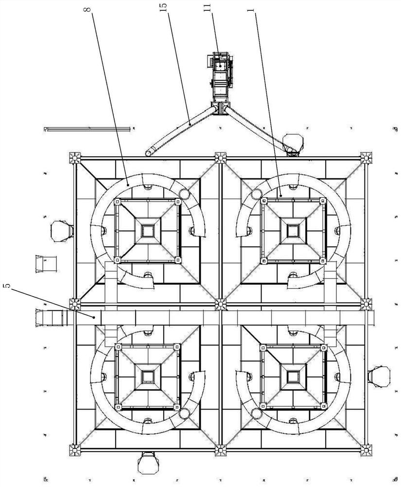
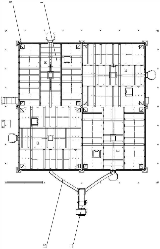
[0042] A configuration example of the above-described embodiment of the present embodiment is substantially the same, the main difference is: the barn is provided with a plurality of main body 1, and spaced, the outer periphery of each granary body 1 are set with said insulation housing 2. That is, each holding a barn housing body 2 a pair, corresponding to the food in order to be able to fill the lumen of the body 1 of the barn, which is a specific configuration of: further comprising insulation disposed outside of the housing 2 of the hoisting machine 11, to enhance the unit 11 and a port grain into the grain scraper conveyor communication port, the scraper conveyor 12 is located at the grain silos port 12 just above the main body 1, and the scraper conveyor 12 through an input port grain food conduit 13 insulation penetrating the housing 2 communicates with the intake port granary bread body 1, there can be input to the pipe 13 plugging food or valve means 1...


PUM


Abstract

The invention belongs to the technical field of grain storage equipment, and particularly relates to a circulating heat preservation granary for brown rice or rice, which comprises a granary body, the periphery of the granary body is sleeved with a heat preservation outer cover, a heat preservation space is formed between the heat preservation outer cover and the granary body, a blowing cooler arranged on the outer side of the heat preservation outer cover, the air outlet end of the blowing cooler penetrates into the heat preservation outer cover through an air conveying pipeline and communicates with the bottom of an inner cavity of the granary body, an air passing window is formed in the wall face of the granary body, and an exhaust port is formed in the heat preservation outer cover. Cold air is blown into the bottom of the inner cavity of the granary body through the blowing cooler so as to cool grains in the inner cavity of the granary body, and the cold air blown into the inner cavity of the granary body is discharged into the heat preservation space so as to cool the wall face of the granary body and is finally recycled at the exhaust port. The circulating heat preservation granary can realize air cooling the inner cavity and the wall face of the granary body at the same time, and is small in energy consumption, uniform in cooling and better in cooling effect.

Description

Technical field: [0001] The present invention belongs to technical field of food storage equipment, rice or brown rice in particular to a heat cycle granary. Background technique: [0002] Granary grain storage grain storage requires low temperature to ensure safety, prevent food spoilage. By controlling food grain during storage stack temperature is maintained at a low temperature 15 ℃ or quasi-low temperature of 20 ℃, thus delaying the aging food and food due to their own fission phenomenon caused by respiration. [0003] Chinese utility model patent conventional (Publication No. Authorization: CN212436453U) one kind of water-cooling systems granary disclosed, which comprises a bottom portion disposed on the bottom side of silos or tanks arranged at the top of a barn and two water tanks, a water tank connected to the water-cooling unit, the water tank and a water tank through the water supply pipe and a plurality of two axially connected to the return pipe through an outer wall...

Claims


Application Information

Patent Timeline
IPC IPC(8): A01F25/14A01F25/22
CPCA01F25/14A01F25/22Y02A40/51
Inventor 余继琅朱广飞郭连兴
Owner TAIZHOU YIMING MASCH CO LTD
Why Eureka
Try Eureka