Check patentability & draft patents in minutes with Patsnap Eureka AI!

Numerical control machine tool

A technology of CNC machine tools and racks, which is applied in the direction of automatic control devices, metal processing machinery parts, measuring/indicating equipment, etc., can solve the problems of not being able to control the yield rate stably, reduce the number of test knives, increase the service life, and avoid The effect of contact

Inactive Publication Date: 2021-12-17
义万青
View PDF0 Cites 0 Cited by
  • Summary
  • Abstract
  • Description
  • Claims
  • Application Information

AI Technical Summary

Problems solved by technology

[0004] The purpose of the present invention is to solve the influencing factors in the processing process in the prior art, which are basically handed over to the operator to monitor and correct. These solutions cannot control the yield problem stably, and the proposed CNC machine tool

Method used


Image

  • Numerical control machine tool
  • Numerical control machine tool
  • Numerical control machine tool

Examples


Embodiment Construction

[0023] The following will clearly and completely describe the technical solutions in the embodiments of the present invention with reference to the accompanying drawings in the embodiments of the present invention. Obviously, the described embodiments are only some, not all, embodiments of the present invention.

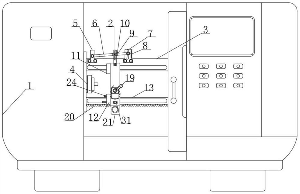
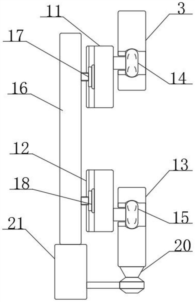
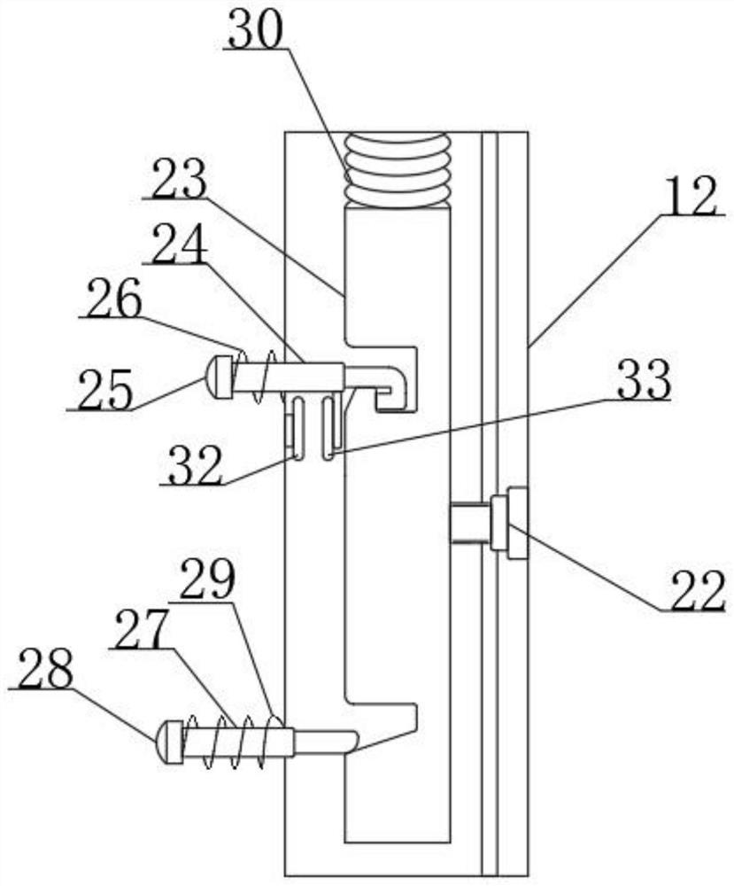
[0024] refer to Figure 1-4 , a CNC machine tool, including a frame 1 and a first vertical bar 2, the inner walls on both sides of the frame 1 are fixedly connected to the first cross bar 3, the inner wall on one side of the frame 1 is fixedly connected to the fixture 4, and the first cross bar 3 is close to the side of the fixture 4 The upper end is fixedly connected to the first fixed frame 5, the first fixed frame 5 is connected to the inclined bar 6 in rotation, the upper end of the first cross bar 3 away from the clamp 4 is fixedly connected to the second fixed frame 7, and the side wall of the second fixed frame 7 is provided with an arc-shaped chute , the side...


PUM


Abstract

The invention discloses a numerical control machine tool which comprises a rack and a first vertical rod. First transverse rods are fixedly connected to the inner walls of the two sides of the rack, a clamp is fixedly connected to the inner wall of one side of the rack, first fixing frames are fixedly connected to the upper ends of the sides, close to the clamp, of the transverse rods, and the first fixing frames are rotationally connected with inclined rods; and the upper ends of the sides, away from the clamp, of the first transverse rods are fixedly connected with second fixing frames, an arc-shaped sliding groove is formed in the side wall of each second fixing frame, the side, away from the clamp, of each inclined rod is slidably connected with the corresponding arc-shaped sliding groove, the side wall of each second fixing frame is fixedly connected with a graduated scale, each inclined rod is sleeved with a sliding sleeve, the front side wall of each sliding sleeve is fixedly connected with a first adjuster, and a sliding groove is formed in the side wall of the first vertical rod. The included angle between the inclined rods and the horizontal direction can be adjusted according to machining requirements to change the height of a cutter on a second vertical rod, a second rubber block at the end of a fourth transverse rod makes contact with the inner side wall of the rack for extrusion, a driving motor stops running, the cutter is prevented from making contact with the clamp, and the service life of the cutter is prolonged.

Description

technical field [0001] The invention relates to the technical field of numerical control machine tools, in particular to numerical control machine tools. Background technique [0002] CNC machine tool is the abbreviation of numerical control machine tool, which is an automatic machine tool equipped with a program control system. The control system can logically process programs with control codes or other symbolic instructions, decode them, express them in coded numbers, and input them into the numerical control device through the information carrier. After calculation and processing, various control signals are sent by the numerical control device to control the movement of the machine tool, and the parts are automatically processed according to the shape and size required by the drawing. CNC machine tools solve complex, precise, small-batch, and multi-variety parts processing problems. It is a flexible, high-efficiency automatic machine tool that represents the developmen...

Claims


Application Information

Patent Timeline
IPC IPC(8): B23Q17/22B23Q15/22
CPCB23Q17/2208B23Q17/22B23Q15/22
Inventor 义万青
Owner 义万青
Features
  • R&D
  • Intellectual Property
  • Life Sciences
  • Materials
  • Tech Scout
  • Unparalleled Data Quality
  • Higher Quality Content
  • 60% Fewer Hallucinations
Learn More