Surface printing equipment for machining in textile industry

A technology of mechanical processing and textile industry, applied in the field of surface printing equipment for mechanical processing in the textile industry, to achieve the effect of preventing wrinkling, cleaning the surface of the fabric, and good color fastness

Pending Publication Date: 2021-12-17
WUXI INST OF ARTS & TECH
View PDF10 Cites 0 Cited by
  • Summary
  • Abstract
  • Description
  • Claims
  • Application Information

AI Technical Summary

Problems solved by technology

[0004] The object of the present invention is to provide a kind of surface printing equipment for mechanical processing of textile industry, which is more suitable for the printing work of small patterns of single tone, and solves the problems raised by the background technology

Method used


Image

  • Surface printing equipment for machining in textile industry
  • Surface printing equipment for machining in textile industry
  • Surface printing equipment for machining in textile industry

Examples


Embodiment 1

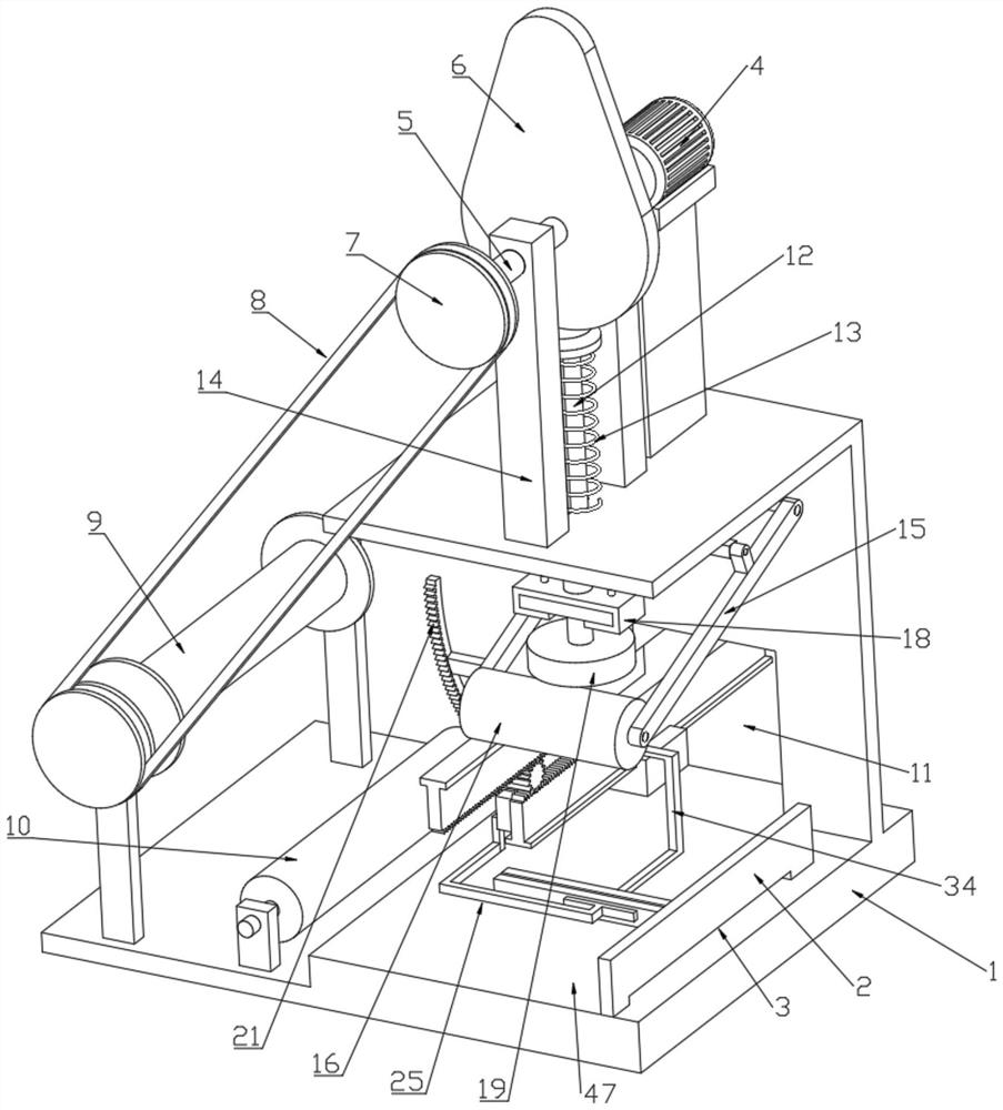
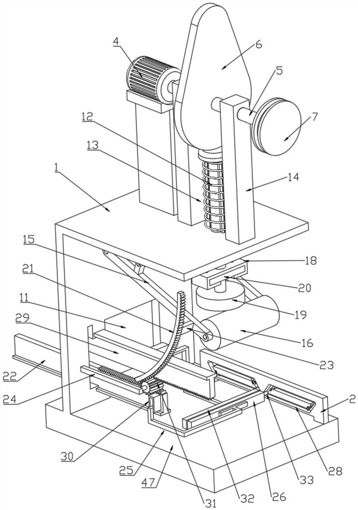
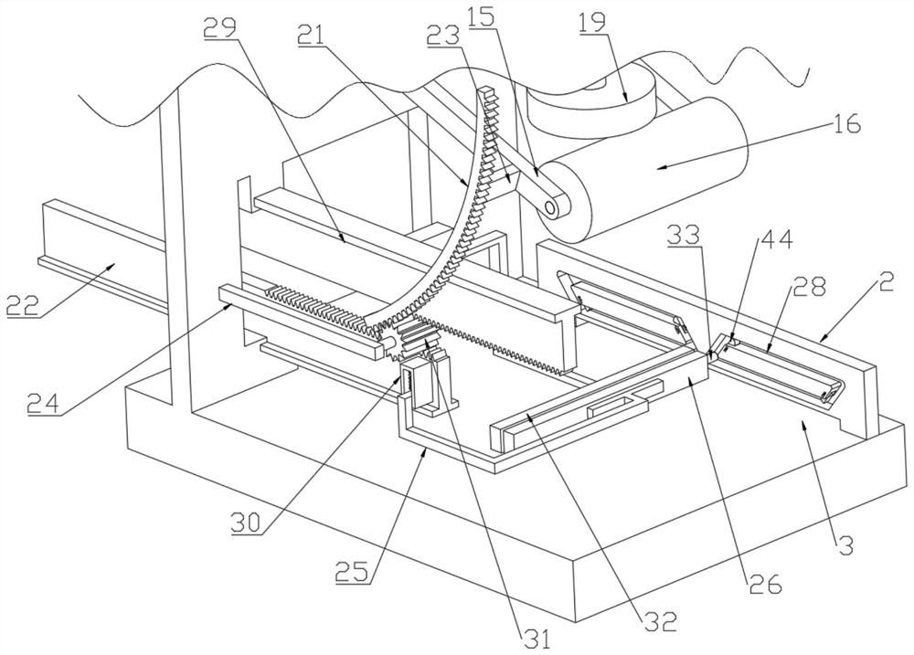
[0032] see figure 1 , figure 2 and Figure 11 , a kind of surface printing equipment for mechanical processing of the textile industry, comprising a machine tool 1, a printing device is arranged on the machine tool 1, the printing device includes a motor 4 fixedly connected to the machine tool 1 through a boss, the output shaft of the motor 4 is fixedly connected with a rotating rod 5. The upper surface of the machine tool 1 is fixedly connected with the support rod 14 which is rotationally connected with the rotary rod 5. The part of the rotary rod 5 located between the support rod 14 and the motor 4 is fixedly connected with the cam 6. The upper surface of the machine tool 1 is provided with a The pressure rod 12 that can slide up and down along the through hole, the upper end of the pressure rod 12 is against the arc-shaped contour surface of the cam 6, the part of the outer wall of the pressure rod 12 located on the upper surface of the machine tool 1 is provided with a ...

Embodiment 2

[0049] see Figure 9 and Figure 10 , in this embodiment, other structures remain unchanged, and the present invention also provides another structural form of the oil replenishment roller 16, further, an oil replenishment rod 51 is arranged inside the oil replenishment roller 16 along its length direction, and the oil replenishment rod The two ends of 51 expose the oil supply roller 16 and are rotatably connected on the fixed rod one 15. The oil replenishment rod 51 passes through the fixed rod one 15 and is connected with the oil box 49 arranged on the side of the fixed rod one 15. The oil box 49 An oil replenishment port 50 is arranged at the upper end, and a threaded cover is arranged on the oil replenishment port 50. The oil replenishment roller 16 is made of sponge material, and the oil replenishment rod 51 is hollow, and a plurality of capillary holes are opened on the wall. Compared with Embodiment 1, oil can be continuously supplied to the oil replenishing rod 51 thr...


PUM


Abstract

The invention discloses surface printing equipment for machining in the textile industry. The equipment comprises a machine tool, a printing device is arranged on the machine tool, the printing device comprises a motor fixedly connected to the upper end of the machine tool through a boss, an output shaft of the motor is fixedly connected with a rotating rod, the upper surface of the machine tool is fixedly connected with a supporting rod, the rotating rod is rotationally connected to the upper surface of the machine tool through the supporting rod, a cam is fixedly connected to the rotating rod, the upper end of the machine tool is glidingly connected with a pressing rod, the upper end of the pressing rod abuts against the arc-shaped contour surface of the cam, part of the outer wall, located at the upper end of the machine tool, of the pressing rod is sleeved with a spring, the outer wall of the pressing rod is provided with a limiting protrusion, the lower end of the pressing rod is fixedly connected with a printing block, a roller is arranged on the left side of the machine tool, a rotatable winding drum is arranged in the position, located on the left side of the roller, of the machine tool, rotating discs are arranged at the end, away from the motor, of the winding drum and the end, away from the motor, of the rotating rod, the two rotating discs are in transmission connection through a belt, and a slide way is arranged on the machine tool. The equipment is more suitable for printing of small patterns with single colors.

Description

technical field [0001] The invention relates to the technical field of textile printing, in particular to a surface printing device for textile mechanical processing. Background technique [0002] Stamp, a certificate used to seal official documents in the old days; refers to tax stamps. Sold by the government and affixed to contracts, certificates, etc., as a special printed matter for taxes. Now also refers to the pattern printed on the textile fabric. [0003] At present, in order to ensure the recognizability of their own products, clothing products usually print their own trademarks on the clothes to ensure the recognizability of the products and facilitate publicity. Often such icons are small patterns with a single tone. In addition, some minimalist clothes will only be printed with small patterns in a single color. However, most of the current printing equipment is more suitable for large and multi-color patterns, and is not suitable for small patterns of single t...

Claims


Application Information

Patent Timeline
IPC IPC(8): B41F1/06B41F1/08B41F1/26B41F1/46B41F23/00B65H18/10B65H23/34
CPCB41F1/06B41F1/08B41F1/265B41F1/26B41F1/46B41F23/00B65H18/10B65H23/34
Inventor 裴红蕾陈珊
Owner WUXI INST OF ARTS & TECH
Why Eureka
Try Eureka