Shaft transmission tricycle capable of swinging

A tricycle and shaft transmission technology, applied in the direction of motor vehicles, rotary transmission devices, bicycles, etc., can solve the problems of complex assembly process, poor reliability and low assembly efficiency, and achieve the effect of ensuring transmission performance, high reliability and simple structure

Pending Publication Date: 2021-12-17
宁波兴隆巨创机电科技有限公司
View PDF0 Cites 0 Cited by
  • Summary
  • Abstract
  • Description
  • Claims
  • Application Information

AI Technical Summary

Problems solved by technology

But in above-mentioned technical scheme, power needs just can arrive driving rear wheel 110 through first chain 106, first transmission sprocket 103, multi-stage universal joint 105, second transmission sprocket 104, second chain 108, rear sprocket 109 Rotation belongs to multi-stage transmission, the transmission loss is large, and the parts of the traditional system are greatly increased, the assembly process is complicated, the two sprockets linked by the same chain have a large wheelbase, and there are two sets of chain transmission mechanisms, which have poor reliability. The ground clearance of the transmission system is small, it is easy to scratch and collide with ground objects during riding, the hidden danger of chain falling off cannot be solved, the reliability is poor, the number of transmission parts is large, and the assembly efficiency is low

Method used


Image

  • Shaft transmission tricycle capable of swinging
  • Shaft transmission tricycle capable of swinging
  • Shaft transmission tricycle capable of swinging

Examples


Embodiment 1

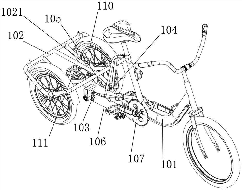
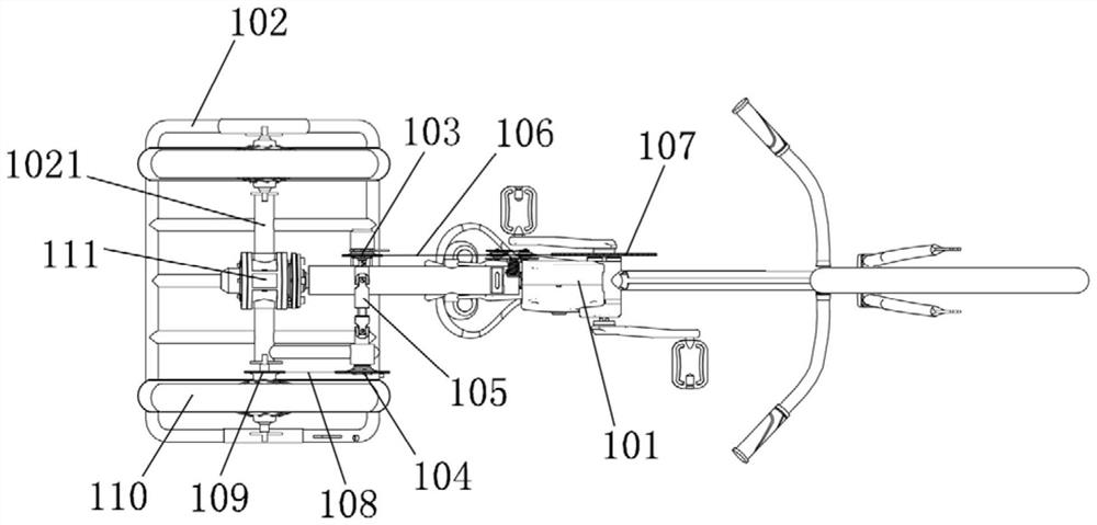
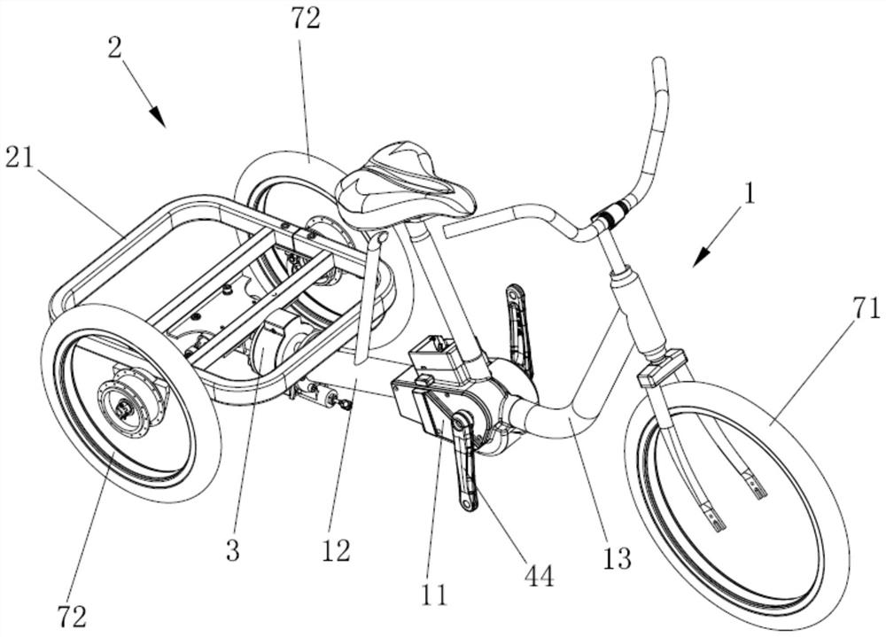
[0049] see Figure 3 to Figure 15 According to the embodiment of the swingable shaft drive tricycle provided by the invention, it comprises a front frame 1, a rear frame 2 and a transmission mechanism, and the front frame 1 is provided with a front wheel 71 (the front wheel in the accompanying drawing is a structural schematic diagram ), two rear wheels 72 are symmetrically arranged on the rear frame 2 (the rear wheels in the accompanying drawings are structural schematic diagrams), and the front frame 1 is swingably connected with the rear frame 2 through a swing mechanism 3 , the transmission mechanism includes a first torque output assembly 4 arranged on the front frame 1, a second torque output assembly 5 arranged on the rear frame 2, and the first torque output assembly 4 passes through the transmission The shaft 6 transmits the torque to the second torque output assembly 5; the second torque output assembly 5 cooperates with at least one of the two rear wheels 72; the mi...

Embodiment 2

[0065] The structure of this embodiment is substantially the same as that of the above-mentioned first embodiment, only the structure of the first torque output assembly is different. Cranks 44 at both ends of the central shaft 41 , the central shaft 41 drives the transmission shaft 6 through the first gear pair. The first torque output assembly 4 has a simple structure, few parts and convenient assembly.


PUM


Abstract

The invention provides a shaft transmission tricycle capable of swinging. The shaft transmission tricycle comprises a front tricycle frame, a rear tricycle frame and a transmission mechanism, the front tricycle frame is connected with the rear tricycle frame through a swinging mechanism, and the transmission mechanism comprises a first torque output assembly arranged on the front tricycle frame and a second torque output assembly arranged on the rear tricycle frame. The first torque output assembly transmits torque to the second torque output assembly through a transmission shaft. The second torque output assembly is in linkage fit with at least one of the two rear wheels. Compared with the prior art, the shaft transmission tricycle capable of swinging has the following advantages that the problem that in the prior art, when the front tricycle frame and the rear tricycle frame swing, the transmission system needs to swing along with the tricycle frames, and consequently the transmission reliability is poor is solved; and secondly, the problems that in the prior art, the chain is prone to falling off due to bumping and vibration, the riding experience is affected, and even the safety is affected are solved.

Description

technical field [0001] The invention relates to the field of tricycles, in particular to a swingable shaft-driven tricycle. Background technique [0002] Pedal-type tricycle is a more commonly used light vehicle in daily life. It has the same portability as a bicycle, and can load more articles at the same time. With the advancement of technology, in order to save the rider's physical strength, electric power-assisted tricycles have appeared, mainly relying on the torque sensor at the crankshaft to detect the signal of the crankshaft rotation, and then the controller controls the motor to provide power for the driving wheels of the tricycle , thereby saving the energy of the cyclist. This kind of power-assisted tricycle is essentially different from the electric motorcycle tricycle. For example, the way to control the rotation of the motor is different. The electric power-assisted tricycle does not have an accelerator on the handlebar. The rider drives the crankshaft throug...

Claims


Application Information

Patent Timeline
IPC IPC(8): B62M17/00B62K5/06B62K5/027B62M6/90B62M6/50
CPCB62M17/00B62K5/06B62K5/027B62M6/90B62M6/50
Inventor 方建华
Owner 宁波兴隆巨创机电科技有限公司
Why Eureka
Try Eureka