Rail movement type anti-shielding security and protection camera device

A technology of orbital movement and camera device, applied in the field of camera, can solve problems such as limited monitoring angle of view, reduction of the number of motors used, and blocking by criminals

Active Publication Date: 2021-12-17
CHONGQING THREE GORGES UNIV
View PDF7 Cites 2 Cited by
  • Summary
  • Abstract
  • Description
  • Claims
  • Application Information

AI Technical Summary

Problems solved by technology

[0003] At present, the security monitoring camera equipment is installed on the building when it is in use, and it can only be adjusted slightly in a fixed place. The monitoring angle of school, bank and administrative office building is limited, and it is affected by the height of the building. It is easy to be blocked by criminals. For example, in the existing patented technology CN112714283A, a U-shaped plate is used, and it is equipped with a drive mechanism, a wire release mechanism, a transmission chain and a guide sprocket group. The U-shaped motion track moves, which can be moved to the back of the wall to expand the monitoring field of view. A set of motors drives the transmission chain, and at the same time drives the wire-releasing mechanism to perform wire-releasing or rewinding movements, reducing the number of motors used and Reduce the failure rate of the motor, but although this design can partially expand the monitoring field of view, it cannot actively remove obstacles and actively avoid obstacles when blocked by foreign objects. In addition, tremors will occur during the movement of the camera, which will affect the shooting picture; the existing CN112019718A in other patented technologies includes a camera, a support seat is provided below the camera, a distance sensor for detecting whether there is an obstruction in front of the camera is provided on the camera, a security mechanism is provided above the support seat, and the security mechanism includes a protective cover and an obstacle-clearing assembly arranged on the protective cover for clearing the obstruction, wherein the obstacle-clearing assembly is used to push the front obstruction through the screw drive assembly. Average removal effect

Method used


Image

  • Rail movement type anti-shielding security and protection camera device
  • Rail movement type anti-shielding security and protection camera device
  • Rail movement type anti-shielding security and protection camera device

Examples


Embodiment 1

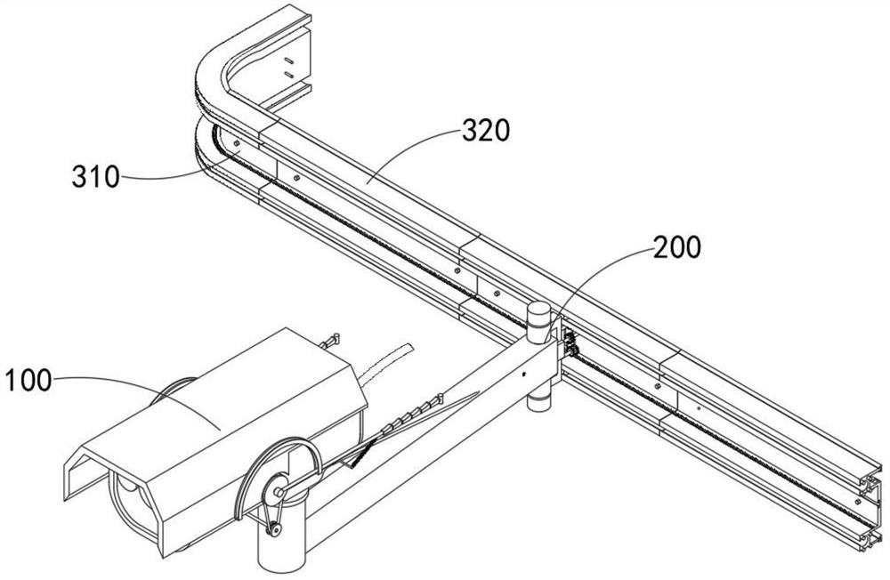
[0048] combine figure 2 , 3 , 7 and 9, a kind of orbital motion anti-blocking security camera device provided by the present invention includes an anti-blocking mechanism 100, a driving mechanism 200 and an assembled track mechanism 300, and the anti-blocking mechanism 100 is installed on the driving mechanism 200. In addition, the drive The mechanism 200 is movably installed in the assembled track mechanism 300 .

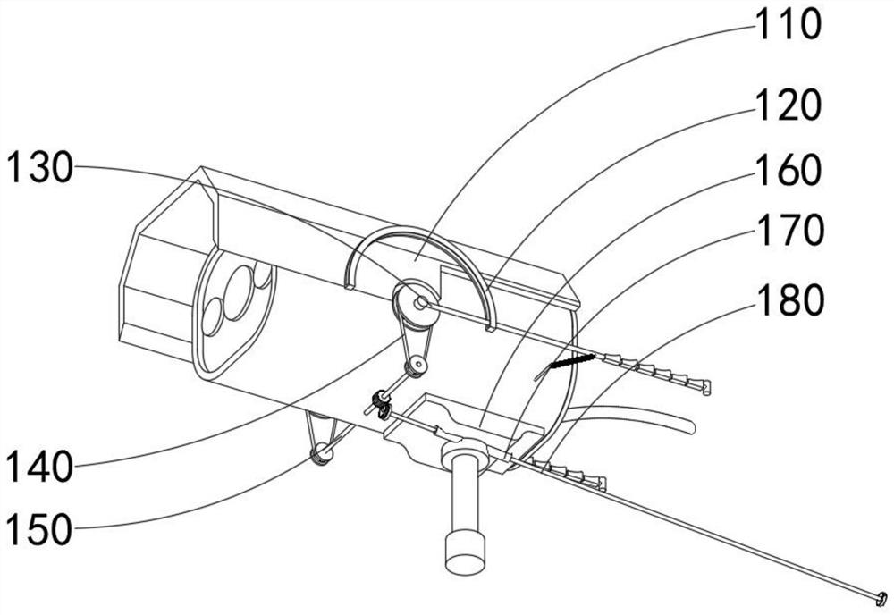
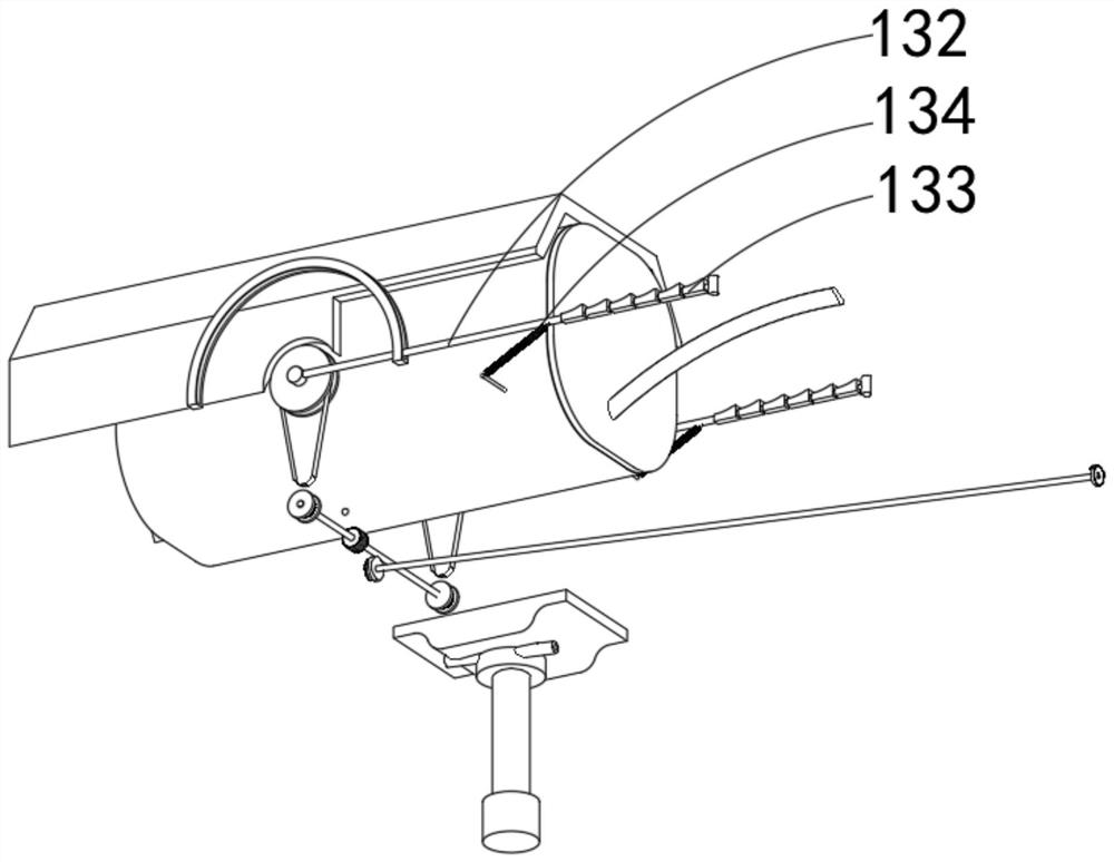
[0049] The anti-blocking mechanism 100 includes a camera 110, a limit clip 120, an overturning assembly 130, a chain 140, a transmission member 150, a base 160, an inclined tube 170, and a deflection gear rod 180, and the overturning assembly 130 also includes a gear plate 131, a cross bar 132, Block 133 and extension spring 134, driving mechanism 200 includes force arm 210, column 220, fixed frame 230, cabinet combination 240, power rod 250, first transmission member 260, second transmission member 270 and rolling member 280, assembling track mechanism 300 incl...

Embodiment 2

[0052] combine figure 2 and 3 As shown, in the above embodiment, two limit clips 120 for constraining the turning track of the toothed disc 131 are fixedly installed on both sides of the exterior of the camera 110, and a tension spring 134 is installed in the middle of the toothed disc 131, so that It can make the tooth plate 131 quickly return to the initial state after taking out the obstacle, and the block 133 is made of rubber, and the rubber friction resistance is relatively large, so that the fast removal of the obstacle plastic bag can be facilitated. When the top of the deflection gear rod 180 When deflecting the middle gear of the transmission member 150, under the limit action of the camera 110, to ensure its stable operation, the intermittent transmission of the outer end gear of the servo motor in the chassis combination 240 to the bottom gear of the deflection gear rod 180 is used. Thereby people can conveniently control cross bar 132 to carry out flipping motio...

Embodiment 3

[0054] combine Figure 7 As shown, in the above embodiment, the anti-blocking mechanism 100 is connected with the driving mechanism 200 by using the force arm 210, and the cavity inside the force arm 210 is used as the deflection gear rod 180 and the outer end gear of the servo motor in the chassis combination 240 The engagement of the parts utilizes the adaptation of the spherical rollers at the outer end of the rolling member 280 to the spherical chute inside the track 321, thereby reducing the frictional resistance when the device moves. The driving mechanism 200 also includes a moment arm 210 installed at the bottom of the base 160, The column 220 plugged in at one end of the moment arm 210 is installed on the fixed frame 230 outside the column 220, and the driving mechanism 200 also includes a rolling member 280 installed on the top and bottom of the outer side of the fixed frame 230, and the rolling member 280 is formed by a T-shaped insertion rod. It is made by connecti...


PUM


Abstract

The invention discloses a rail movement type anti-shielding security and protection camera device. The rail movement type anti-shielding security and protection camera device comprises an anti-blocking mechanism, a driving mechanism and an assembled rail mechanism, wherein the anti-blocking mechanism comprises an overturning combination, a transmission part in transmission connection outside the overturning combination, and a deflection toothed bar engaged outside the transmission part; and the driving mechanism comprises a machine case combination, a power rod connected to the inner end of the machine case combination, a first transmission part and a second transmission part, wherein the first transmission part and the second transmission part are connected outside the power rod in a transmission manner; and the assembled rail mechanism comprises a straight rail combination. The deflection toothed bar is arranged to drive the transmission part, gears at the two ends of the outer portion of the transmission part are used for driving chains and fluted discs to rotate, and due to intermittent meshing transmission of half tooth openings in the gears at the outer end of the deflection toothed bar and the fluted discs at the outer end of a servo motor in the machine case combination, and cross rods can be conveniently overturned along the inner side of limiting clamps, so that the purpose of removing sheltering objects is achieved in sequence through overturning of the cross rods.

Description

technical field [0001] The invention relates to the field of photography, in particular to an orbital movement anti-blocking security camera device. Background technique [0002] Surveillance cameras are quasi-cameras used in security. Its pixels and resolution are higher than those of computer video heads, and lower than professional digital cameras or DVs. Most of the security surveillance cameras are single video capture devices, which are widely used in schools, Companies, banks, transportation, safe cities and other security fields. [0003] At present, the security monitoring camera equipment is installed on the building when it is in use, and it can only be adjusted slightly in a fixed place. The monitoring angle of school, bank and administrative office building is limited, and it is affected by the height of the building. It is easy to be blocked by criminals. For example, in the existing patented technology CN112714283A, a U-shaped plate is used, and it is equippe...

Claims


Application Information

Patent Timeline
Patent Type & Authority Applications(China)
IPC IPC(8): F16M13/02F16M11/20H04N5/225
CPCF16M13/02F16M11/2085H04N23/50Y02E10/50
Inventor 闫东方冯玉明张伟明鑫何春霖
Owner CHONGQING THREE GORGES UNIV
Why Eureka
Try Eureka