Energy-saving boiler

An energy-saving boiler technology, applied to steam boilers, steam boiler accessories, steam boiler components, etc., can solve the problems of reducing the heating effect of the device, not being able to use heat effectively, and affecting the service life of the device, so as to reduce pressure and improve Effects of stability and utilization improvement

Pending Publication Date: 2021-12-17
黄涌凯
View PDF1 Cites 2 Cited by
  • Summary
  • Abstract
  • Description
  • Claims
  • Application Information

AI Technical Summary

Problems solved by technology

[0006] Aiming at the deficiencies of the existing technology, the present invention provides an energy-saving boiler, which solves the problem that the heat generated by heating cannot be effectively utilized, resulting in waste of heat, and the device is prone to uneven heating during heating, which reduces the heating of the device. The effect will cause damage to the device and affect the service life of the device

Method used


Image

  • Energy-saving boiler
  • Energy-saving boiler
  • Energy-saving boiler

Examples


Embodiment 1

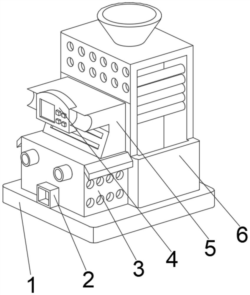
[0033] see Figure 1-2 , the present invention provides a technical solution: an energy-saving boiler, including a base plate 1, a heating device 6 is fixedly connected to the top right side of the base plate 1, and a heating box is fixedly connected to the bottom of the outer wall on the left side of the heating device 6 at the top of the base plate 1 3. The right side of the top of the heating box 3 is fixedly connected with a heat insulation board 5, and the top of the left outer wall of the heat insulation board 5 is provided with a control panel 4, and the right outer wall of the control panel 4 runs through the heat insulation board 5 and extends to the heat insulation board Inside of 5, the middle position of the left side outer wall bottom of heating box 3 is provided with air vent 2.

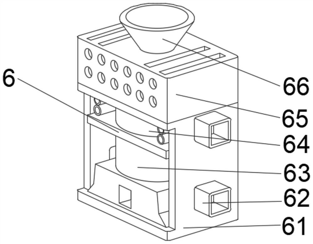
[0034] The heating device 6 includes a boiler body 61, the outer walls of both sides of the boiler body 61 are provided with connecting pipes 62, the bottom of the inner cavity of the b...

Embodiment 2

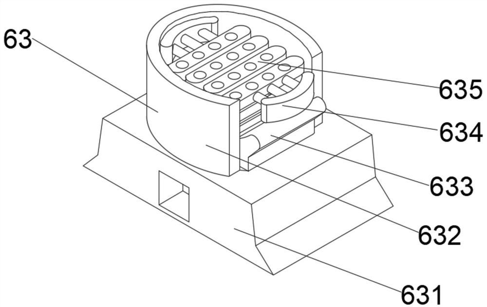
[0037] see Figure 1-4 , on the basis of Embodiment 1, the present invention provides a technical solution: Component 1 of the preheating mechanism 63 includes a heat exchange seat 631, and the middle position of the top of the heat exchange seat 631 is fixedly connected with an insulating layer 633, and the heat exchange seat 631 The top is located on both sides of the insulation layer 633 and is provided with a sealed shell 632. The bottom of the sealed shell 632 runs through the heat exchange seat 631 and extends to the inside of the heat exchange seat 631. The top of the inner wall on both sides of the sealed shell 632 is provided with a temperature control member 634. A heat conducting frame 635 is fixedly connected to a side of the temperature element 634 away from the sealing shell 632 .

[0038] Wherein, the component one of protection mechanism 64 comprises bottom set plate 641, and the top middle position of bottom set plate 641 is fixedly connected with water storag...

Embodiment 3

[0041] see Figure 1-6 , on the basis of Embodiment 1 and Embodiment 2, the present invention provides a technical solution: component 2 of the preheating mechanism 63 includes a fixed connection frame d1, and the bottom of the inner cavity of the fixed connection frame d1 is fixedly connected with an auxiliary preheating element d2 , the top of the auxiliary preheating part d2 is fixedly connected with the piston plate d3, the top of the piston plate d3 is fixedly connected with the preheating induction part d4, and the front middle part of the preheating induction part d4 is provided with a cooling hole d5.

[0042] Wherein, the second component of the protective mechanism 64 includes a protective shell t1, the middle position of the inner cavity top of the protective shell t1 is fixedly connected with the heating main body t2, and the inner cavity bottom of the protective shell t1 is located on both sides of the heating main body t2. The top of the plate d5 is fixedly conne...


PUM


Abstract

The invention discloses an energy-saving boiler. The boiler comprises a bottom plate, a heating device is fixedly connected to the right side of the top of the bottom plate, a heating box is fixedly connected to the position, located at the bottom of the outer wall of the left side of the heating device, of the top of the bottom plate, a heat insulation plate is fixedly connected to the right side of the top of the heating box, a control panel is arranged at the top of the outer wall of the left side of the heat insulation plate, and a ventilation opening is formed in the middle of the bottom of the outer wall of the left side of the heating box. The invention relates to the technical field of boilers. According to the energy-saving boiler, heat generated by electrifying of the heating box can be transferred through connection with a preheating mechanism, meanwhile, the heat insulation plate can insulate the influence of the heat, dust generated by traditional heating can be conveniently reduced, the situation that water is scattered in the water adding process is avoided, then the utilization rate of the heat generated by heating can be improved, the boiler has good stability during working, the boiler can be uniformly heated, and the service life of the boilder is effectively prolonged.

Description

technical field [0001] The invention relates to the technical field of boilers, in particular to an energy-saving boiler. Background technique [0002] The boiler is an energy conversion device. The energy input into the boiler includes chemical energy and electric energy in the fuel. The boiler outputs steam, high-temperature water or organic heat carrier with a certain amount of heat energy. The hot water or steam generated in the boiler can be directly used for industrial The heat energy required for production and people's life can also be converted into mechanical energy through a steam power plant, or converted into electrical energy through a generator. Boilers that provide hot water are called hot water boilers, which are mainly used in daily life. For a small amount of application, the boiler that generates steam is a steam boiler, often referred to as a boiler, and is mostly used in thermal power stations, ships, locomotives, and industrial and mining enterprises. ...

Claims


Application Information

Patent Timeline
Patent Type & Authority Applications(China)
IPC IPC(8): F22B1/28F22B37/00
CPCF22B1/28F22B37/00
Inventor 黄涌凯
Owner 黄涌凯
Why Eureka
Try Eureka