
Rapid method for forming array antenna pattern

An array antenna and pattern technology, applied in special data processing applications, complex mathematical operations, instruments, etc., to achieve hardware price and operating cost control, good application prospects, and the effect of small calculation amount

Pending Publication Date: 2021-12-17
SUZHOU WEIMO ELECTRONIC INFORMATION TECH CO LTD
View PDF0 Cites 0 Cited by
  • Summary
  • Abstract
  • Description
  • Claims
  • Application Information

AI Technical Summary

Problems solved by technology

[0004] In order to overcome the above-mentioned defects and deficiencies of the existing array antenna complex pattern formation method, the present invention provides a set of solutions: the present invention adopts a non-iterative analysis method, which can quickly simulate the required pattern, and the calculation amount of this method is small. Low configuration requirements for hardware environment and computing resources, which can meet the requirements of real-time applications

Method used


Image

  • Rapid method for forming array antenna pattern
  • Rapid method for forming array antenna pattern
  • Rapid method for forming array antenna pattern

Examples


Embodiment 1

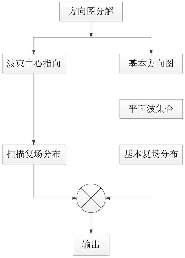
[0074] Embodiment 1: a kind of fast method that array antenna pattern forms (referring to appendix figure 1 ),include:

[0075] Step 1: Decompose the pattern of the array antenna to obtain the direction of the center of the irradiation beam and the pattern of the basic shape, where:

[0076] The spherical coordinate angle parameter corresponding to the center of the irradiation beam is refers to the direction in which the center of the pattern of the array antenna is located;

[0077] The basic shape pattern G 0 , refers to the shape of the array antenna pattern when the center of the irradiation beam is not considered, that is, the shape when the center direction of the array antenna pattern is the normal direction.

[0078] Step 2: Decompose the basic shape pattern to obtain the irradiated plane wave set. The specific steps are as follows:

[0079] According to the width of the default needle beam when the array antenna is fed in the same phase, the image of the basic s...

Embodiment 2

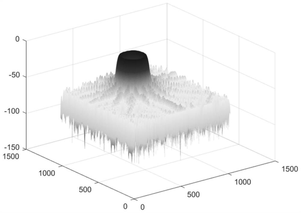
[0108] Embodiment 2: the rapid formation of ring beam pattern (referring to appended figure 2 )

[0109] Using the method of Embodiment 1, the ring beam pattern is quickly formed

[0110] The working frequency is 30GHz, the spacing between antenna elements is half a wavelength, the array size is 50*50, and the ring beam is synthesized. The center of the beam is pointed at a pitch of 30°. figure 2 .

Embodiment 3

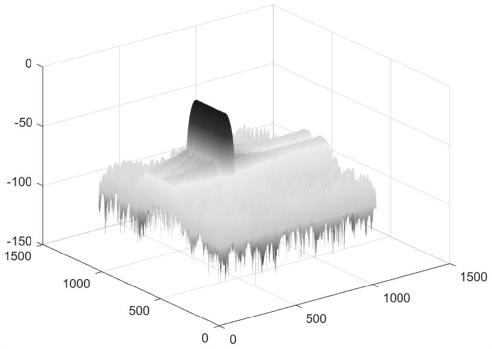
[0111] Embodiment 3: the rapid formation of fan beam pattern (referring to appended image 3 )

[0112] Utilize the method of Embodiment 1 to quickly form a fan beam pattern

[0113] The working frequency is 30GHz, the spacing between antenna elements is half a wavelength, the array size is 50*50, and the fan beam is synthesized. The center of the beam is directed at an azimuth of 20°. image 3 .


PUM


Abstract

The invention relates to the technical field of optical imaging, microwave imaging, radar detection, sonar, ultrasonic imaging and target detection and wireless communication based on media such as sound, light and electricity, in particular to a rapid method for forming an array antenna pattern and application of the rapid method in the fields. According to the method, an array antenna directional diagram is decomposed into a series of sets of irradiation plane waves with different directions, phases and intensities, complex field distribution of the plane wave sets irradiated on an array aperture is calculated, and the result is array antenna unit amplitude and phase weighting coefficients corresponding to the required directional diagram. A non-iterative analysis method is adopted, the needed directional diagram can be quickly simulated, the requirement of real-time application is met, in addition, the method is small in calculation amount, the configuration requirement for the hardware environment and computing resources is low, and the hardware price and the operation cost are effectively controlled.

Description

technical field [0001] The present invention relates to the technical fields of optical imaging, microwave imaging, radar detection, sonar, ultrasonic imaging, and target detection and wireless communication based on media such as sound, light, electricity, etc., and specifically relates to a fast method for forming an array antenna pattern and its application in the above-mentioned applications in various fields. Background technique [0002] Most of the existing array antenna complex pattern formation methods use optimization methods, that is, use various optimization algorithms to optimize the amplitude and phase distribution of array elements, and then synthesize the required complex shape pattern. [0003] However, the above optimization methods have obvious defects and deficiencies. On the one hand, most of the optimization algorithms currently used are iterative algorithms, which require multiple iterations to obtain the required pattern, so the algorithm speed is slo...

Claims


Application Information

Patent Timeline
Patent Type & Authority Applications(China)
IPC IPC(8): G06F17/14G06F17/15G06F17/18
CPCG06F17/142G06F17/15G06F17/18
Inventor 张继康张继龙俞晓琳张艺恒宋雨花
Owner SUZHOU WEIMO ELECTRONIC INFORMATION TECH CO LTD
Learn More