Radio frequency circuit and mobile terminal

A mobile terminal and radio frequency circuit technology, applied in the radio frequency field, can solve the problems of unfavorable antenna performance, high device cost, and large loss

Active Publication Date: 2021-12-17
HUIZHOU TCL MOBILE COMM CO LTD
View PDF12 Cites 0 Cited by
  • Summary
  • Abstract
  • Description
  • Claims
  • Application Information

AI Technical Summary

Problems solved by technology

[0005] In view of the above deficiencies in the prior art, the purpose of the present invention is to provide a radio frequency circuit and a mobile terminal, aiming at solving the problem of high device cost and large loss in the prior art when it is necessary to support a medium + high CA combination. Problems with unfavorable antenna performance

Method used


Image

  • Radio frequency circuit and mobile terminal
  • Radio frequency circuit and mobile terminal

Examples


Embodiment 1

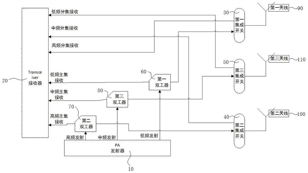
[0050] like figure 2 As shown, the present invention provides a radio frequency circuit, including: a transmitter 10 , a receiver 20 and a first antenna 90 . The radio frequency circuit further includes: a first integrated switch 30 and a first duplexer 60 . The first antenna 90 is connected to the first integrated switch 30, and the output end of the first integrated switch 30 is connected to the high frequency diversity receiving end of the receiver 20, and the receiver 20 receives the The first antenna 90 supplies the high frequency signal to and distributed by the first integrated switch 30 . The first duplexer 60 is respectively connected to the first integrated switch 30 , the low frequency transmitting end of the transmitter 10 and the low frequency main set receiving end of the receiver 20 . The first duplexer 60 is used for receiving the signal sent by the low frequency transmitting end of the transmitter 10 , and sending the signal to the first integrated switch 3...

Embodiment 2

[0053] On the basis of Example 1, as figure 2 As shown, the radio frequency circuit further includes: a second antenna 100 , a second integrated switch 40 , and a second duplexer 70 . The second antenna 100 is connected to the second integrated switch 40, and the output end of the second integrated switch 40 is connected to the IF diversity receiving end of the receiver 20, and the receiver 20 receives the second integrated frequency diversity receiving end through the IF diversity receiving end. The antenna 100 supplies the intermediate frequency signal to and distributed by the second integrated switch 40 . The second duplexer 70 is respectively connected to the second integrated switch 40 , the high frequency transmitting end of the transmitter 10 and the high frequency main set receiving end of the receiver 20 . The second duplexer 70 is used for receiving the signal sent by the high-frequency transmitting end of the transmitter 10, and sending the signal to the second i...

Embodiment 3

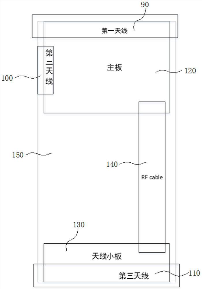
[0060] On the basis of Embodiment 1 and Embodiment 2, as figure 1 As shown, the present invention further provides a mobile terminal, including a mobile terminal body 150 , the mobile terminal further includes the radio frequency circuit described in Embodiment 1 and Embodiment 2, and the radio frequency circuit is arranged on the mobile terminal body 150 Inside. The mobile terminal can implement the main sets of low, medium and high frequencies through separate antennas in the radio frequency circuit, and can maximally meet the CA combination requirements between various frequency bands.


PUM


Abstract

The invention discloses a radio frequency circuit and a mobile terminal. The radio frequency circuit comprises a transmitter, a receiver and a first antenna. The radio frequency circuit further comprises a first integrated switch and a first duplexer. The first antenna is connected with a first integrated switch, and an output end of the first integrated switch is connected with a high-frequency diversity receiving end of the receiver; and the first duplexer is respectively connected with the first integrated switch, the low-frequency transmitting end of the transmitter and the low-frequency main set receiving end of the receiver, and through the arrangement of multiple groups, the problems of high device cost, large loss and unfavorable antenna performance when medium and high CA combination needs to be supported in the prior art are solved.

Description

technical field [0001] The present invention relates to the field of radio frequency technology, and in particular, to a radio frequency circuit and a mobile terminal. Background technique [0002] With the rapid development of the mobile Internet today, the holdings of smart mobile terminals have grown rapidly, driving a substantial increase in global data traffic. People increasingly want to transmit more data content wirelessly, such as data transmission in more frequency bands. [0003] Antennas in the prior art, in order to support the carrier aggregation (CA) function, need to use expensive radio frequency devices to combine each frequency band in one antenna. In addition, the loss of the device is large, which is detrimental to the performance of the antenna. How to make each antenna support all frequency bands is a problem that needs to be solved at present. [0004] Therefore, the existing technology still needs to be improved and developed. SUMMARY OF THE INVEN...

Claims


Application Information

Patent Timeline
Patent Type & Authority Applications(China)
IPC IPC(8): H04B1/40
CPCH04B1/40Y02D30/70
Inventor 陈卫张攀李潇
Owner HUIZHOU TCL MOBILE COMM CO LTD
Why Eureka
Try Eureka