Laser radar signal receiving off-axis spherical reflection focusing optical system

A focusing optical system and signal receiving technology, applied in optics, optical components, condensers, etc., can solve the problems of high cost, low signal receiving efficiency, difficult processing of parabolic primary mirror, etc., to achieve low cost, good optical focusing performance, The effect of increasing the signal receiving area

Inactive Publication Date: 2012-11-14
INST OF APPLIED ELECTRONICS CHINA ACAD OF ENG PHYSICS +1
View PDF4 Cites 0 Cited by
  • Summary
  • Abstract
  • Description
  • Claims
  • Application Information

AI Technical Summary

Problems solved by technology

[0004] In order to overcome the shortcomings of low signal receiving efficiency, difficult processing of the parabolic primary mirror and high cost in the prior art of laser radar signal receiving optical system, the present invention provides a laser radar signal receiving off-axis spherical reflective focusing optical system

Method used


Image

  • Laser radar signal receiving off-axis spherical reflection focusing optical system
  • Laser radar signal receiving off-axis spherical reflection focusing optical system

Examples


Embodiment 1

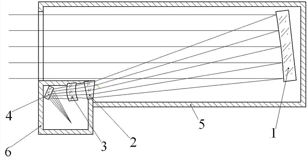
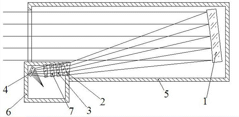
[0018] figure 1 It is a structural schematic diagram of Embodiments 1-3 of a laser radar signal receiving off-axis spherical reflective focusing optical system of the present invention. figure 1 Among them, Embodiment 1 of a laser radar signal receiving off-axis spherical reflective focusing optical system of the present invention includes a main mirror 1, an off-axis aberration correction mirror group 2, a spherical aberration correction mirror group 3, a plane mirror 4, and a main lens barrel 5 , Cassette 6. It is used for laser radar signal reception in ultraviolet band, visible light band and infrared band.

[0019] The main reflector 1 is arranged in the main lens barrel 5 to reduce the influence of background stray light; the off-axis aberration correction mirror group 2, the spherical aberration correction mirror group 3, and the plane mirror 4 are arranged in the cassette 6, and the off-axis aberration correction mirror Group 2 is the optical window of the cassette 6...

Embodiment 2

[0026] The basic structure of this embodiment is the same as that of Embodiment 1, except that the diameter of the main reflector 1 is 260 mm, the focal length is 5 times the diameter of the mirror, and the included angle between the reflected optical axis and the incident optical axis is 12°.

[0027] The material of the wedge mirror used in the off-axis aberration correcting mirror group 2 is magnesium fluoride.

[0028] The material of the spherical meniscus lens used in the spherical aberration correction lens group 3 is calcium fluoride.

[0029] The material of plane mirror 4 is quartz glass.

Embodiment 3

[0031] The basic structure of this embodiment is the same as that of Embodiment 1, except that the diameter of the primary reflector 1 is 300 mm, the focal length is 8 times the diameter of the mirror, and the angle between the reflected optical axis and the incident optical axis is 20°.

[0032] The material of the wedge lens used in the off-axis aberration correction lens group 2 is sodium fluoride.

[0033] The material of the spherical meniscus lens used in the spherical aberration correction lens group 3 is calcium fluoride.

[0034] The material of the plane mirror 4 is K4.


PUM


Abstract

The invention discloses a laser radar signal receiving off-axis spherical reflection focusing optical system. A main reflector in the optical system is arranged in a main lens cone, is a spherical mirror, and is aslant arranged relative to an incident optical axis to ensure that a reflection beam is transmitted in an off-axis manner, thus partial receiving apertures are prevented from being shielded due to the fact that a rear optical component is arranged in a receiving optical path and signal receiving area of the main reflector is increased. An off-axis aberration correction lens subassembly, a spherical aberration correction lens subassembly and a plane mirror in the optical system are sequentially arranged in the receiving optical path of the main reflector and closed in a cartridge,the spherical aberration correction lens subassembly is an optical window of the cartridge, the off-axis aberration correction lens subassembly is used for correcting off-axis aberration caused by aslant installation of the main reflector, and the spherical aberration correction lens subassembly is used for correcting spherical aberration caused by using a spherical mirror as the main reflection.The optical system has the advantages of higher optical efficiency, easiness in processing and assembling as well as regulating because the spherical mirror is used as the main reflection, and low cost.

Description

technical field [0001] The invention belongs to the field of laser radar signal receiving optical systems, in particular to a laser radar signal receiving off-axis spherical reflective focusing optical system. It is used for efficient reception and detection of atmospheric scattered laser return signals such as differential absorption lidar and aerosol lidar. Background technique [0002] In systems such as differential absorption lidar and aerosol lidar, in order to realize long-distance gas composition detection and aerosol detection, it is necessary to improve the ability of the lidar signal receiving optical system to collect light signals. At the same time, in order to facilitate popularization and application, the system needs to be simple, reliable and low in cost. [0003] The existing laser radar signal receiving optical system mainly has three forms: 1) Newtonian reflection system: it is composed of a parabolic primary mirror and a plane mirror at 45° to the optic...

Claims


Application Information

Patent Timeline
Patent Type & Authority Patents(China)
IPC IPC(8): G02B19/00G02B7/182G02B5/08G02B1/00
Inventor 叶一东田飞胡大平罗佳田英华王卫民马毅
Owner INST OF APPLIED ELECTRONICS CHINA ACAD OF ENG PHYSICS
Why Eureka
Try Eureka