Multi-mode programmable modulated arc ion plating apparatus controlled by rotary lateral magnetic field

An arc ion plating and transverse magnetic field technology, which is applied in ion implantation plating, sputtering plating, vacuum evaporation plating, etc., can solve the problems of discharge that cannot effectively improve arc spot, poor adjustability, fixed magnetic field potential, etc. Intensity is difficult to mediate and other issues

Inactive Publication Date: 2010-06-09
INST OF METAL RESEARCH - CHINESE ACAD OF SCI
View PDF5 Cites 0 Cited by
  • Summary
  • Abstract
  • Description
  • Claims
  • Application Information

AI Technical Summary

Problems solved by technology

However, this method needs to add a complex mechanical control mechanism; at the same time, the position of the magnetic field is fixed and the intensity is difficult to adjust. It is only a mechanical movement that causes the change of the distribution of the magnetic field, and the adjustability is poor, which cannot effectively improve the arc spot. Discharge, suppress the emission of particles; and it involves many problems such as sealing and cooling, so it is difficult to popularize and apply

Method used


Image

  • Multi-mode programmable modulated arc ion plating apparatus controlled by rotary lateral magnetic field
  • Multi-mode programmable modulated arc ion plating apparatus controlled by rotary lateral magnetic field
  • Multi-mode programmable modulated arc ion plating apparatus controlled by rotary lateral magnetic field

Examples


Embodiment 1

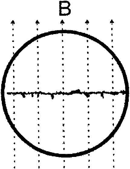
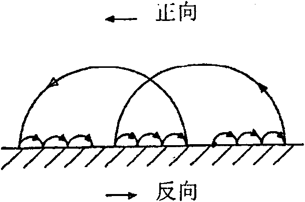
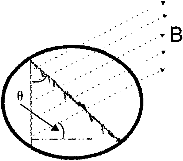
[0077] An important feature of arc ion plating is that the arc spot discharge forms a high temperature area near it, and it will radiate to other places in the vacuum chamber at the same time, and the space of the vacuum chamber is limited, and the space around the target is also limited, so the arc source When designing, it will be difficult to break through if the thinking is limited to the limited space in the vacuum chamber. Especially for the design of the rotating magnetic field that controls the movement of the arc spot, if the rotating magnetic field generator is placed around the target in the vacuum chamber, it will involve limitations in size, material, etc. Although better results can be achieved when conditions permit, but For industrial production that requires large-area deposition and long-term work, it will be limited. In the face of wider and simpler applications, new innovations and breakthroughs are required.

[0078] Figure 3(a)-3(c) It is a schematic d...

Embodiment 2

[0087] Since arc ion plating mainly depends on the discharge of cathode spots on the target surface to deposit the required film, it is a point source, so there is the problem of uneven distribution of plasma in the transmission space, resulting in uneven film deposition. Embodiment 2 is the same as Embodiment 1, except that a focusing magnetic field is applied near the back of the substrate clamp to improve the distribution of plasma in the transmission space, increase the density of ions at the substrate, and increase the deposition rate and deposition uniformity. Figure 5 It is the schematic diagram of the arc ion plating deposition equipment controlled by the rotating magnetic field in embodiment 2. The specific structure is as follows:

[0088] Arc ion plating deposition equipment mainly includes target material 2, rotating magnetic field device 6, water outlet pipe 9, arc pilot coil 10, water outlet 11, water inlet 12, electromagnetic coil 13, nickel-plated pure iron 14...

Embodiment 3

[0092] The difference with embodiment 1 or 2 is:

[0093] Figure 7(a)-Figure 7(b) It is the schematic diagram of the arc ion plating arc source controlled by the rotating magnetic field of embodiment 3. Among them, FIG. 7( a ) is a schematic diagram of the rotating magnetic field generator 6 . Embodiment 3 is a rotating magnetic field generator controlled by two-phase electricity. Four magnetic poles 4 are evenly distributed on the circular closed main magnetic conduction channel to form an integral electromagnetic circuit skeleton. The shape of the magnetic poles is square or circular, and the size According to the size of the space between the main magnetic channel and the target material 2, the material of the skeleton is made of high magnetic permeability material (electrical pure iron or superimposed punched silicon steel sheet). The top end of the magnetic pole 4 is straight or arc-shaped, symmetrically pointing to the center of the surface of the target 2 . FIG. 7( ...


PUM

PropertyMeasurementUnit
thicknessaaaaaaaaaa
thicknessaaaaaaaaaa
thicknessaaaaaaaaaa

Abstract

The invention relates to the field of film preparation, in particular to an arc ion plating device which controls arc point movement by a rotary magnetic field and is controlled by a rotary transversemagnetic field with the multi-mode programmable modulation. The device is provided with a target material, a rotary magnetic field generating device, an electromagnetic coil, an insulating bush, a flange, a vacuum chamber and a matrix holder, wherein, the matrix holder and the target material are arranged inside the vacuum chamber, the front face of the target material is opposite to the matrix holder, the back of the target material is provided with electromagnetic coils, the rotary magnetic field generating device arranged outside the vacuum chamber is sheathed on a flange sleeve or an furnace body tube around the target material, and insulation is used for protection between the rotary magnetic field generating device and the flange sleeve or the furnace body tube. By controlling the arc point movement by the rotary transverse magnetic field with the multi-mode programmable modulation, the arc ion plating device can improve the discharge mode and the operating stability of the arcpoint, improve the etching uniformity and the utilization rate of the target material and reduce the large particle emission of the target material. The arc ion plating device is used for preparing high-quality films and functional films and expanding the application range of the arc ion plating.

Description

technical field [0001] The invention relates to the field of thin film preparation, in particular to an arc ion plating device controlled by a rotating transverse magnetic field controlled by a rotating magnetic field using a rotating magnetic field to control the movement of the arc spot. form, control the movement of the arc spot, improve the uniformity of target etching, reduce or inhibit the emission of large particles of the target, and prepare high-quality thin films. Background technique [0002] Arc ion plating is one of the most important technologies in industrial coating production and scientific research. Due to its simple structure, high ionization rate (70%-80%), high energy of incident particles, good diffraction, it can realize low temperature deposition, etc. A series of advantages have enabled the arc ion plating technology to develop rapidly and be widely used, showing great economic benefits and industrial application prospects. [0003] Arc ion plating ...

Claims


Application Information

Patent Timeline
Patent Type & Authority Patents(China)
IPC IPC(8): C23C14/35C23C14/54
Inventor 肖金泉郎文昌孙超宫骏赵彦辉闻立时
Owner INST OF METAL RESEARCH - CHINESE ACAD OF SCI
Why Eureka
Try Eureka