
Fan device and communication equipment

A fan and mounting hole technology, applied in mechanical equipment, structural parts of electrical equipment, parts of pumping devices for elastic fluids, etc., to achieve the effect of reducing space and cost, accurate alignment, and small space

Pending Publication Date: 2021-12-17
ZTE CORP
View PDF0 Cites 0 Cited by
  • Summary
  • Abstract
  • Description
  • Claims
  • Application Information

AI Technical Summary

Problems solved by technology

[0004] The main purpose of the embodiments of the present invention is to provide a fan device, which overcomes the disadvantage that the fan in the prior art needs to be connected with the fan and the shock-absorbing nails through various brackets

Method used


Image

  • Fan device and communication equipment
  • Fan device and communication equipment
  • Fan device and communication equipment

Examples


Embodiment Construction

[0036] It should be understood that the specific embodiments described here are only used to explain the present invention, not to limit the present invention.

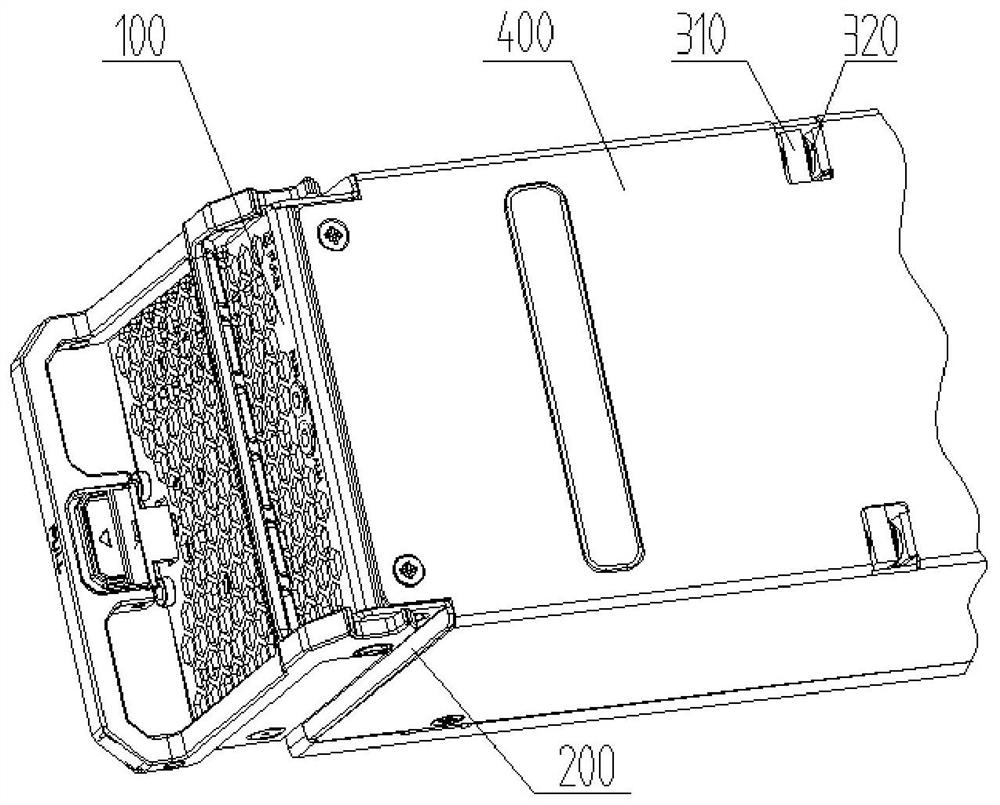
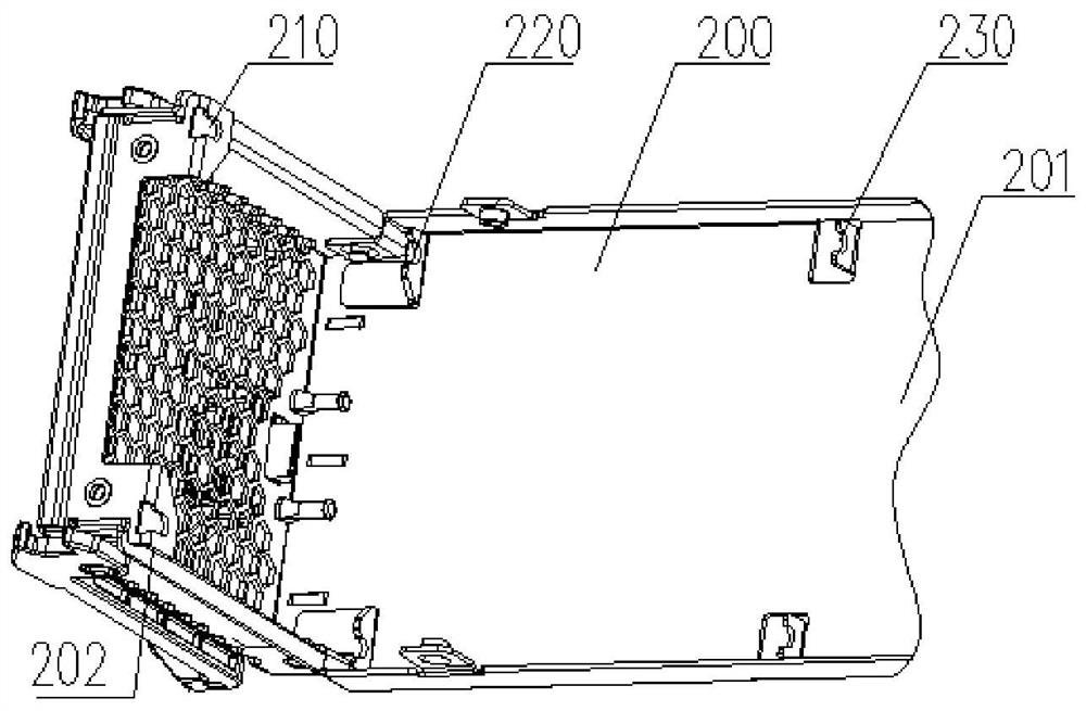
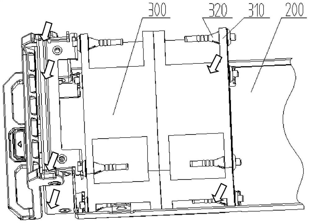
[0037] Such as figure 1 , image 3 , Figure 8 As shown, it is a schematic diagram of different angles of the fan device provided by the embodiment of the present invention, which can be quickly installed in the space enclosed by the box body 200 and the cover plate 400 of the fan sub-box 100. It can be seen from the figure that the fan device of the embodiment of the present invention The device includes: a fan assembly 300 placed in the box body 200, and further includes: directly connecting the upper part of one side of the fan assembly with the side plate 202 of the box body (see figure 2 ) the first connecting structure on the upper part; the second connecting structure directly connecting the upper part of the other side of the fan assembly and the cover plate; the third connecting structure directly connecti...


PUM


Abstract

The invention discloses a fan device and communication equipment, and belongs to the field of communication and electronic equipment. The fan device is used for being arranged in a space defined by a box body and a cover plate of the fan plug-in box, comprises a fan assembly, and further comprises: a first connecting structure, which is connected with the upper portion of one side of the fan assembly and the upper portion of a side plate of the box body, a second connecting structure, which is connected with the upper part of the other side of the fan assembly and the cover plate; and a third connecting structure, which is connected with two sides of the lower part of the fan assembly and two sides of the bottom plate of the box body. According to the fan device, the fan and the damping nails do not need to be connected together through various supports, and the problem that damping cannot be conducted on the fan due to the fact that the internal space of a box body of a fan plug-in box or a fan module is small or limited is solved.

Description

technical field [0001] The invention relates to the fields of communication and electronic equipment, in particular to a rapidly-installable fan device for a fan box and communication equipment with the device. Background technique [0002] Most of the equipment involved in the field of communication and electronic equipment needs to use the fan box (or fan module) to ventilate and dissipate the equipment system. The structure of the fan box (or fan module) is various. With the modern quality High requirements, and modern manufacturing technology also put forward higher requirements for production efficiency and maintainability of communication and electronic equipment. Good, high-efficiency production, and a compact fan assembly structure is required. [0003] In the prior art structure that adopts the fan box for heat dissipation, when connecting the fan to the fan box, it is necessary to first install brackets on both sides of the fan, and then connect the bracket and th...

Claims


Application Information

Patent Timeline
Patent Type & Authority Applications(China)
IPC IPC(8): H05K7/20
CPCH05K7/20172H05K7/20F04D29/66
Inventor 杨世林高磊
Owner ZTE CORP
Learn More