
Cooling system

A technology of cooling system and cooling fluid, which is applied in the direction of engine cooling, heating/cooling equipment, power plant cooling combination arrangement, etc., and can solve problems such as difficult balance

Pending Publication Date: 2021-12-17
DENSO CORP
View PDF2 Cites 0 Cited by
  • Summary
  • Abstract
  • Description
  • Claims
  • Application Information

AI Technical Summary

Problems solved by technology

In this way, in the cooling system described in Cited Document 1, since there is a trade-off relationship between the controllability of the air volume and the mountability, it is difficult to balance both.

Method used


Image

  • Cooling system
  • Cooling system
  • Cooling system

Examples


no. 1 approach >

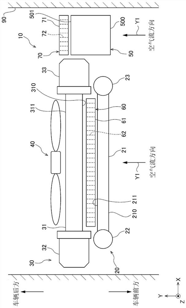
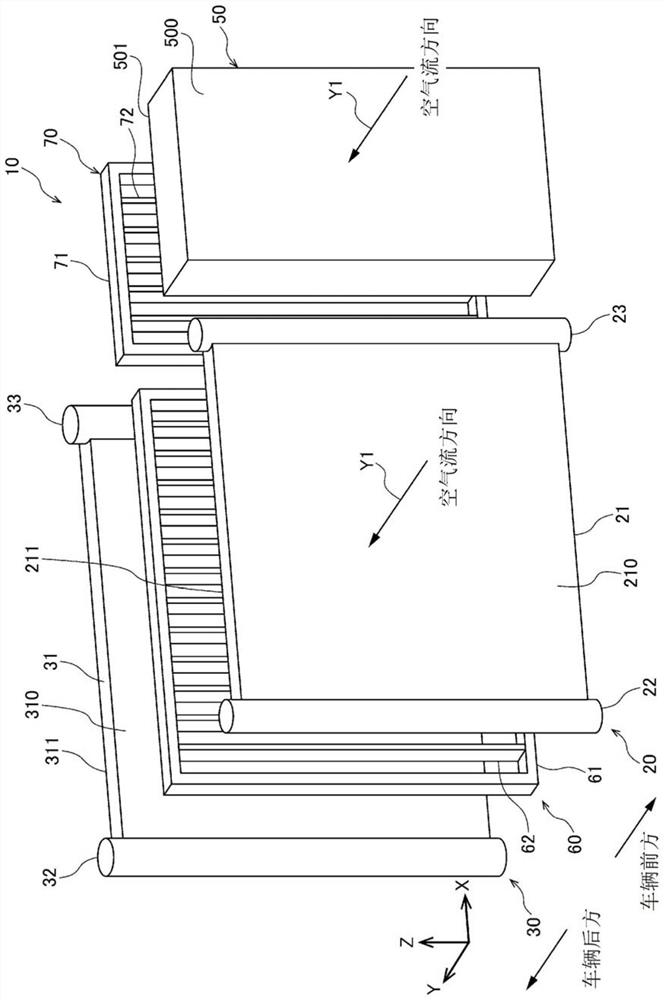
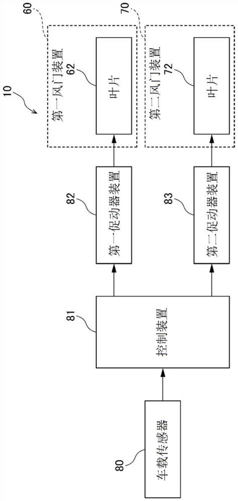
[0028] first of all, yes figure 1 The cooling system 10 of the first embodiment shown will be described. Cooling system 10 is mounted on a vehicle. The cooling system 10 includes a condenser 20 , a radiator 30 , a fan unit 40 , an intercooler 50 , a first damper unit 60 , and a second damper unit 70 . These elements are arranged in the air passage 90 in the engine compartment of the vehicle. In the air passage 90 , air introduced from the grille opening of the vehicle, that is, traveling wind flows in a direction indicated by an arrow Y1 . In the present embodiment, the condenser 20 and the radiator 30 correspond to a specific heat exchange unit, and the intercooler 50 corresponds to a heat exchange unit different from the specific heat exchange unit.

[0029] Hereinafter, for the sake of convenience, the direction indicated by the arrow Y1 is referred to as "airflow direction Y1". In addition, the air introduced from the grill opening is called "external air". The direct...

no. 2 approach >

[0067] Next, the cooling system 10 of the second embodiment will be described. Hereinafter, the description will focus on differences from the cooling system 10 of the first embodiment.

[0068] Such as Figure 8As shown, the cooling system 10 of the present embodiment is different from the cooling system 10 of the first embodiment in that the intercooler 50 and the second damper device 70 are not included. Moreover, the core part 31 of the heat sink 30 of this embodiment is divided into the 1st core part 31a and the 2nd core part 31b. The first core part 31a and the second core part 31b are arranged side by side in a direction perpendicular to the airflow direction Y1. High-temperature cooling water flows inside each tube of the first core portion 31a. High-temperature cooling water is cooling water used for cooling, for example, an engine. In the first core portion 31a, the high-temperature cooling water is cooled by heat exchange between the high-temperature cooling wat...


PUM


Abstract

A cooling system (10) is provided with: a plurality of heat-exchanging parts (20, 30, 50); a shutter device (60); and a control unit (81). The control unit determines whether the amount of air flowing through a heat-exchanging part (50) different from specific heat-exchanging parts (20, 30) needs to be increased, and reduces the amount of air flowing through the specific heat-exchanging parts while increasing the amount of air flowing through the different heat-exchanging part by changing the opening degree of the shutter device toward the closing direction upon determination that the amount of air flowing through the different heat-exchanging part needs to be increased.

Description

[0001] Cross-references to related applications [0002] This application is based on and claims the benefit of priority of Japanese Patent Application No. 2019-091111 filed on May 14, 2019, and the entire contents of this patent application are incorporated herein by reference. technical field [0003] The invention relates to a cooling system. Background technique [0004] Conventionally, there is a cooling system described in Patent Document 1 below. The cooling system described in Patent Document 1 has an air volume ratio adjustment guide that adjusts the air volume ratio of the air volume of the running air flowing to the condenser and radiator of the vehicle to the air volume of the running air flowing to the intercooler. . The condenser and the radiator are arranged in line in the flow direction of the traveling wind. The condenser is arranged on the upstream side of the radiator in the flow direction of traveling wind. The intercooler is disposed adjacent to the ...

Claims


Application Information

Patent Timeline
Patent Type & Authority Applications(China)
IPC IPC(8): B60K11/04F01P5/02B60H1/32F01P11/10
CPCF01P5/02F01P11/10B60K11/04B60K11/085Y02T10/88B60H1/32B60H2001/3291
Inventor 真岛康太安田位司三桥拓也
Owner DENSO CORP
Learn More