Integral machining method for Z-shaped reinforcement cage of diaphragm wall

A technology of overall processing and steel cages, applied in the direction of wire processing, building reinforcements, building materials, etc., can solve the problems of difficult operation, complicated process, and existing risks, and achieve simple and clear steps, stable structure, and easy processing and welding Effect

Active Publication Date: 2021-12-21
CHINA RAILWAY 24TH BUREAU GRP
View PDF19 Cites 0 Cited by
  • Summary
  • Abstract
  • Description
  • Claims
  • Application Information

AI Technical Summary

Problems solved by technology

According to the conventional method of processing and manufacturing reinforcement cages with walls, the upper and lower layers of horizontal reinforcement are Z-shaped. When making reinforcement cages, they need to be welded vertically to the ground platform. The operation is not easy, the process is complicated, time-consuming, and there are risks.

Method used


Image

  • Integral machining method for Z-shaped reinforcement cage of diaphragm wall
  • Integral machining method for Z-shaped reinforcement cage of diaphragm wall
  • Integral machining method for Z-shaped reinforcement cage of diaphragm wall

Examples


Embodiment 1

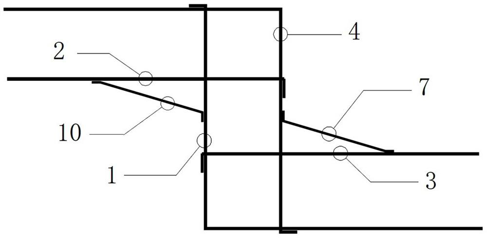
[0031] Embodiment 1: as Figure 1-5 As shown, the present embodiment relates to an overall processing method of a Z-shaped reinforcement cage for a ground connection wall, and the overall processing method includes the following steps:

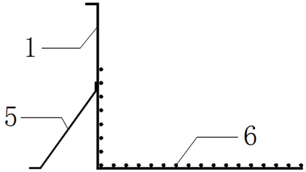
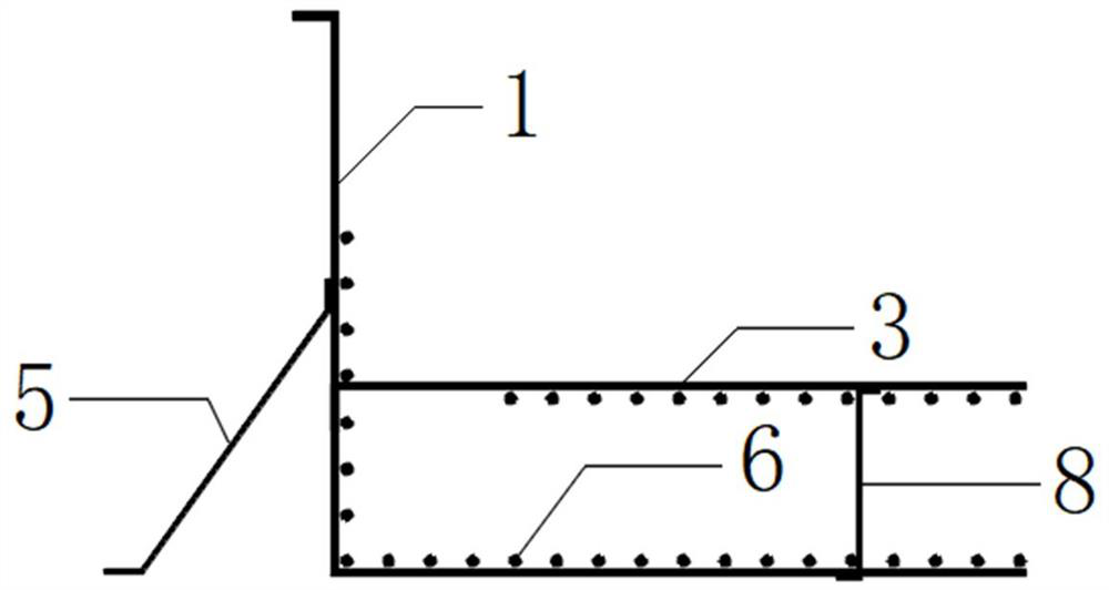
[0032] Step (1): If figure 2 As shown, the lower L-shaped horizontal reinforcement 1 is laid, except for the upper part of the vertical section of the lower L-shaped horizontal reinforcement 1, the longitudinal reinforcement 6 is welded on the inner side of other positions of the lower L-shaped horizontal reinforcement 1 to form the first part of the lower longitudinal truss reinforcement . In addition, the outer side of the vertical section of the lower L-shaped horizontal rib 1 is provided with a first temporary support bracket 5 placed obliquely. One end of the first temporary support bracket 5 is fixed on the ground or the processing platform, and the other end is spot welded to the lower L-shaped horizontal rib 1. Fixed, used to suppor...

Embodiment 2

[0037] Embodiment 2: as Figure 5-7 Shown, a kind of hoisting method of the Z-shaped reinforcement cage of the ground connection wall, the hoisting method comprises the following steps:

[0038] 1. Use the main crane 11, auxiliary crane 12 and auxiliary crane 13 to hoist the Z-shaped reinforcement cage of the ground connection wall, and remove all temporary support brackets. Among them, there are 6 lifting points that can be connected with the main crane 11 on the Z-shaped reinforcement cage of the ground connection wall, which are respectively lifting point a, lifting point b, lifting point c, lifting point d, lifting point e and lifting point Point f, lifting point a and lifting point b are all set at the side of the lower longitudinal truss reinforcement of the Z-shaped reinforcement cage of the ground connection wall, and the lifting point a and lifting point b are respectively located at the lower and upper layers of the lower longitudinal truss reinforcement. Both c and...


PUM


Abstract

The invention discloses an integral machining method of a Z-shaped reinforcement cage of a diaphragm wall. The integral machining method comprises the following steps that lower-layer L-shaped horizontal bars are laid, and longitudinal reinforcements are welded to on the inner sides of the lower-layer L-shaped horizontal bars except the upper parts of vertical sections of the lower-layer L-shaped horizontal bars; upper-layer linear horizontal bars are welded on the vertical sections of the lower-layer L-shaped horizontal bars, and longitudinal reinforcements are welded on the inner sides of the upper-layer linear horizontal bars except one sides, close to the vertical sections of the lower-layer L-shaped horizontal bars, of the upper-layer linear horizontal bars; lower-layer linear horizontal bars are welded at the junction of the vertical sections of the lower-layer L-shaped horizontal bars where the longitudinal reinforcements are welded and the junction of the vertical sections of the lower-layer L-shaped horizontal bars where the longitudinal reinforcements are not welded, and longitudinal steel bars are welded on the inner sides of the lower-layer linear horizontal bars except the horizontal sections of the lower-layer L-shaped horizontal bars and the same sides of the upper-layer linear horizontal bars; and upper-layer L-shaped horizontal bars are welded, and longitudinal reinforcements are welded on the inner sides of the upper-layer linear horizontal bars except one sides, close to the horizontal sections of the lower-layer L-shaped horizontal bars, and the Z-shaped reinforcement cage of the diaphragm wall is obtained.

Description

technical field [0001] The invention relates to the technical field of ground-connected wall steel cages, in particular to an overall processing method for ground-connected wall Z-shaped steel cages. Background technique [0002] There are "one-shaped", "L-shaped" and "Z-shaped" reinforcement cages for the ground connection wall. Its structure is mainly divided into upper and lower layers of steel bars and connecting trusses between them. Ribs, welded and fixed→Welded trusses and reinforcements→Laying longitudinal reinforcements on the lower layer and welding them firmly→Welding bottom protection pads→Trusses and reinforcements were erected and fixed by welding→Welding upper longitudinal reinforcements→Welding upper horizontal reinforcements→Welding Ribs for the upper lifting point → welding additional ribs and protective pads. Among them, the "Z-shaped" ground connection wall is difficult to construct and requires high requirements. It is generally constructed in the way o...

Claims


Application Information

Patent Timeline
Patent Type & Authority Applications(China)
IPC IPC(8): B21F27/10B21F27/12B66C1/12B66C13/08E04C5/06E04G21/14
CPCB21F27/10B21F27/12B21F27/128B66C13/08B66C1/12E04C5/06E04G21/14
Inventor 盛灿军周吟冯江宇李厚荣廖武朱继存樊恒朱克宏
Owner CHINA RAILWAY 24TH BUREAU GRP
Why Eureka
Try Eureka