
Plate pressing device, material pressing and taking method and automatic sorting system.

A press plate and splint technology, which is applied in the direction of auxiliary devices, program-controlled manipulators, manipulators, etc., can solve problems that affect workpiece grasping, affect production efficiency, and workpieces cannot be grasped, and achieve stable operation, simple structure, and low cost. Effect

Active Publication Date: 2021-12-21
SPEEDBOT ROBOTICS CO LTD
View PDF7 Cites 2 Cited by
  • Summary
  • Abstract
  • Description
  • Claims
  • Application Information

AI Technical Summary

Problems solved by technology

[0003] After the scrap falls back, the position deviates from the previous position, which affects the grabbing of the next workpiece without visual repositioning
Waste materials are brought up and down on other workpieces, resulting in failure to grab subsequent workpieces. If the above situation occurs, it is necessary to stop the sorting system and perform human intervention on abnormalities, which will affect production efficiency and cause waste of manpower.

Method used


Image

  • Plate pressing device, material pressing and taking method and automatic sorting system.
  • Plate pressing device, material pressing and taking method and automatic sorting system.
  • Plate pressing device, material pressing and taking method and automatic sorting system.

Examples


Embodiment 1

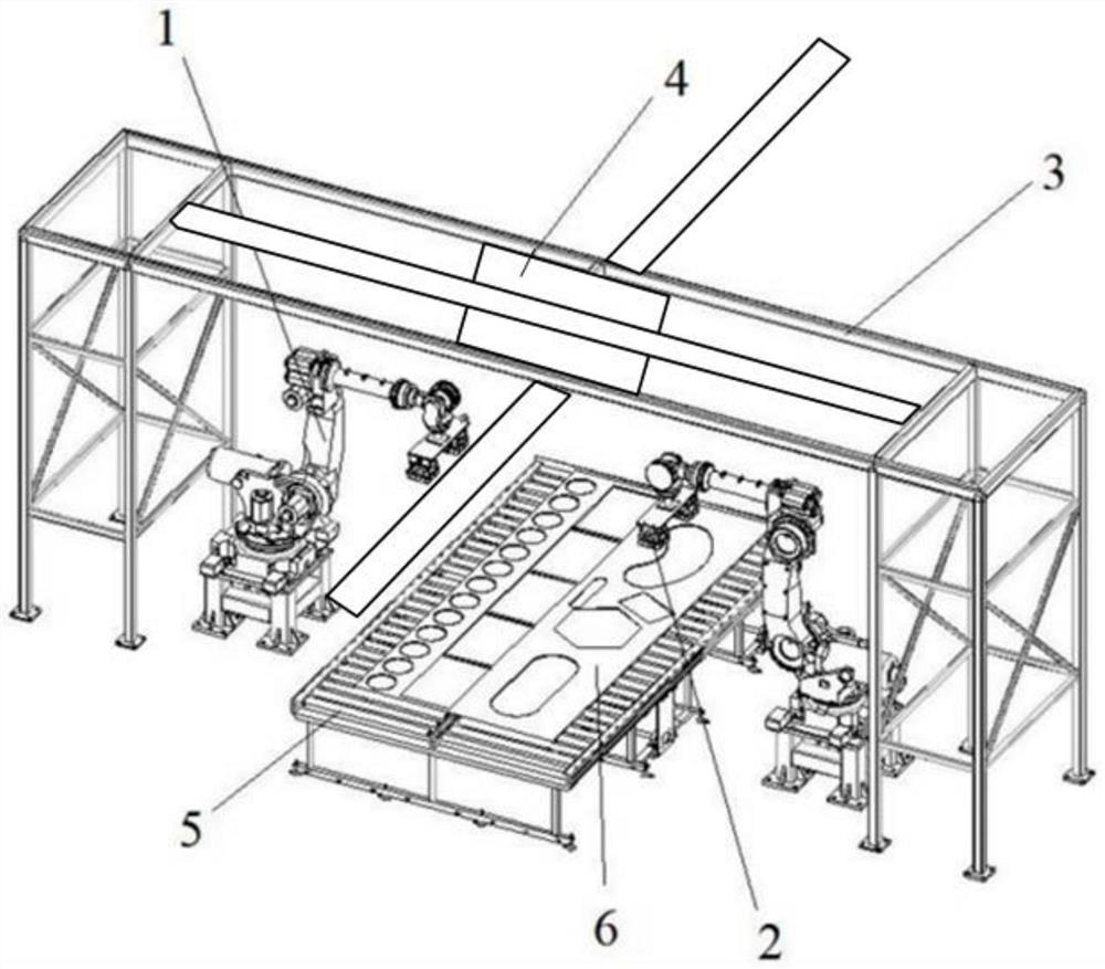
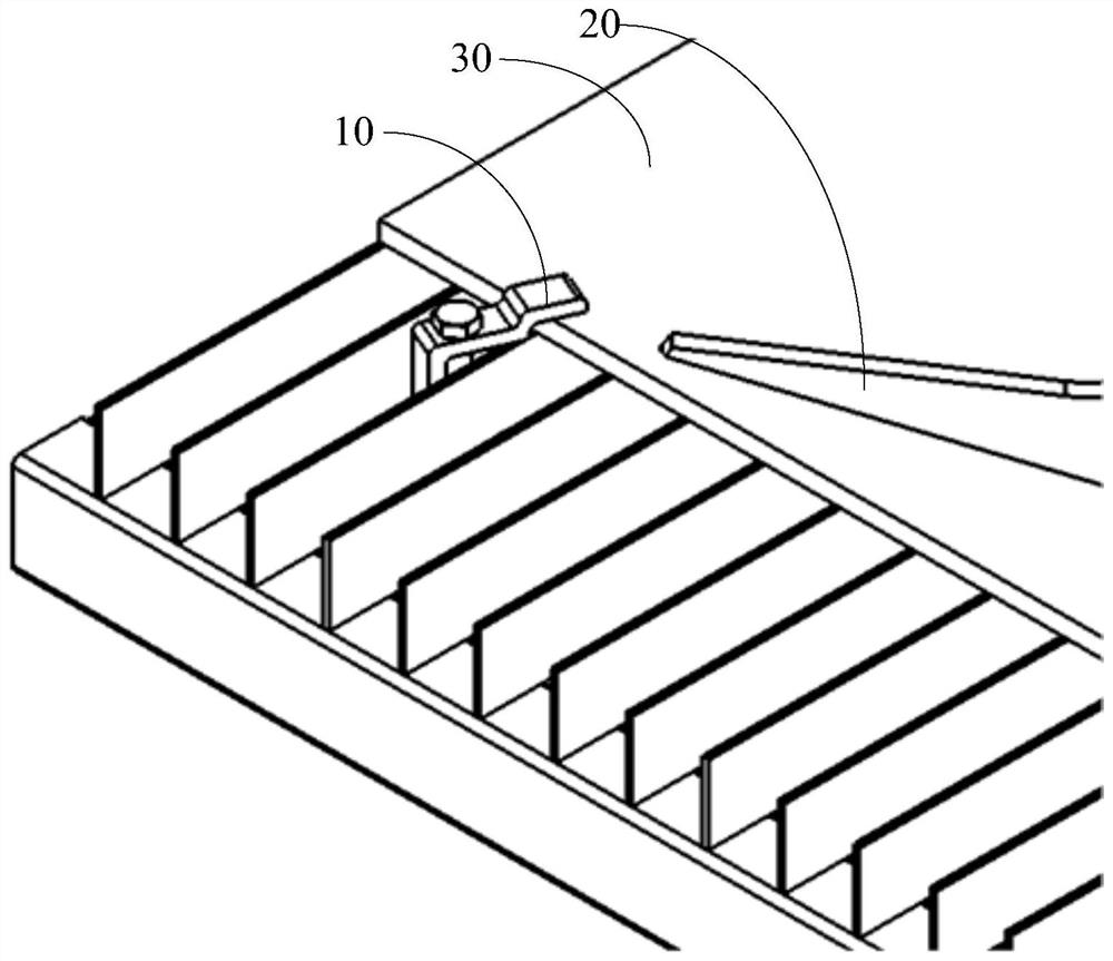
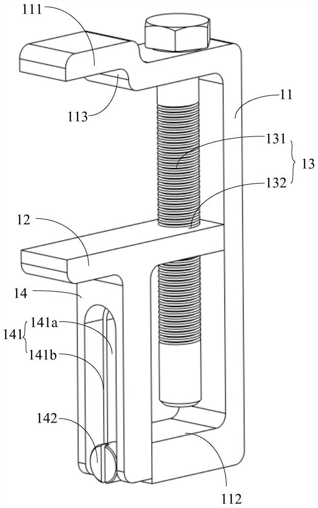
[0047] refer to Figure 1 to Figure 3 , the present invention proposes a platen device, the platen device 10 includes: a base 11, a movable splint 12, a Z-axis driving assembly 13, and a Z-axis sliding assembly 14; One side of the seat 11 is provided with an upper splint 111 and a lower splint 112; the movable splint 12 is movable between the upper splint 111 and the lower splint 112; the movable splint 12 is arranged in parallel with the upper splint 111; The Z-axis driving assembly 13 includes a drive screw 131 provided on the upper clamping plate 111 and a threaded hole 132 provided on the movable clamping plate 12; The sliding block 142 on the top and the sliding rail 141 adapted to the sliding block 142 ; the sliding rail 141 is connected with the movable splint 12 . The Z-axis sliding assembly 14 is used to guide the movable splint 12 close to or away from the upper splint 111; through the Z-axis drive assembly 13, the movable splint 12 approaches or moves away from the...

Embodiment 2

[0057] The present invention also proposes a method for pressing and retrieving materials, referring to image 3 , including the following steps:

[0058] S10 acquires the image information of the cut material sheet; in this step, the image information of the cut material sheet is obtained through the industrial camera arranged above the platen device 10, and the image information is transmitted to the visual recognition module through the PLC.

[0059] S20 obtains the position information of the workpiece 20 according to the image information and nesting map information; the visual recognition module identifies the cut workpiece 20 according to the image information of the material sheet and the nesting map information in the PLC memory, thereby obtaining each workpiece 20 location information. Specifically, the industrial camera takes pictures to obtain the picture information of the workpiece 20, takes the camera as the origin, obtains the polar coordinate information of e...

Embodiment 3

[0071] In another embodiment of the present invention, the planning of the fetching path information and the pressing path information according to the position information of the workpiece 20 further includes the following steps:

[0072] According to the position information of the workpiece 20 and the image information of the material plate, the position information of the waste material 30 is obtained;

[0073] The pressing path information is generated according to the position information of the waste material 30 .

[0074] In this step, the PLC generates picking path information according to the position information of the workpiece 20 in the order of picking up row by row or column by column or S-shaped path.

[0075] The contour model of the clamping plate is projected on the waste material to obtain the position information of the clamping area of ​​the waste material, in which the edge of the waste material cannot overlap with the edge of the movable splint 12 .

...


PUM


Abstract

The invention discloses a plate pressing device, a material pressing and taking method and an automatic sorting system. The plate pressing device comprises a base, a movable clamping plate, a Z-axis driving assembly and a Z-axis sliding assembly, and an upper clamping plate and a lower clamping plate are arranged on one side of the base; the movable clamping plate is movably arranged between the upper clamping plate and the lower clamping plate; and the Z-axis driving assembly comprises a driving screw arranged on the upper clamping plate and a threaded hole formed in the movable clamping plate. The Z-axis sliding assembly comprises a sliding block arranged on the lower clamping plate and a sliding rail matched with the sliding block. The sliding rail is connected with the movable clamping plate. After blanking is completed, the shape and position information of the waste is obtained in combination with an identification vision technology, and material taking path information and material pressing path information are planned according to the position information of a workpiece; an automatic code spraying mechanism is driven according to the material pressing path information, and code spraying marking is conducted on the position where a plate needs to be pressed; and the plate pressing device is installed, so that a material taking mechanical arm can lift and stack the workpieces conveniently, and the problem that waste materials are brought up to intervene in sorting can be solved.

Description

technical field [0001] The invention relates to the field of automatic sorting, and relates to a platen pressing device, a material pressing and retrieving method and an automatic sorting system. Background technique [0002] In the production of modern heavy industry, it generally involves cutting and blanking the plates. Specifically, laser or flame cutting technology is used. After cutting, the workpieces will be automatically sorted through the truss. Specifically, the position of the workpiece can be determined by using visual positioning and recognition technology, and then grasped and stacked by jaws or electromagnetic chucks. After cutting, because the gap between the workpiece and the waste is very small, the workpiece is deformed by gravity or other external forces during the process of grabbing the workpiece, resulting in conflict between the workpiece and the waste, and there is a certain friction force. After the two are separated, the waste will fall back agai...

Claims


Application Information

Patent Timeline
Patent Type & Authority Applications(China)
IPC IPC(8): B25J9/00B25J9/16B23K37/00
CPCB25J9/0096B25J9/0084B25J9/1664B25J9/1666B25J9/1669B23K37/00
Inventor 罗鹏程周敏彭飞
Owner SPEEDBOT ROBOTICS CO LTD
Learn More