
Air take-off and landing system and air take-off and landing method

A technology of take-off and landing platform and flight direction, which is applied in the field of drones, can solve the problems of high take-off and landing site requirements, high failure probability, land occupation, etc., and achieve the effect of flexible transition, low failure probability, and less damage

Pending Publication Date: 2021-12-21
BEIJING JINGDONG QIANSHITECHNOLOGY CO LTD
View PDF5 Cites 1 Cited by
  • Summary
  • Abstract
  • Description
  • Claims
  • Application Information

AI Technical Summary

Problems solved by technology

However, the runway rolling takeoff and landing scheme has high requirements on the takeoff and landing site, and requires a straight and long runway
Furthermore, the failure probability of the catapult-parachute combination scheme is higher than that of the runway roll-off and landing scheme, and it will cause damage to the fixed-wing UAV
In addition, the above two take-off and landing schemes for fixed-wing UAVs need to be completed on the ground, resulting in land occupation and the inability to achieve flexible transitions

Method used


Image

  • Air take-off and landing system and air take-off and landing method
  • Air take-off and landing system and air take-off and landing method
  • Air take-off and landing system and air take-off and landing method

Examples


Embodiment Construction

[0031] Typical embodiments embodying the features and advantages of the present invention will be described in detail in the following description. It should be understood that the present invention can have various changes in different embodiments without departing from the scope of the present invention, and that the description and drawings therein are illustrative in nature and not intended to limit the present invention. invention.

[0032] In the following description of various exemplary embodiments of the invention, reference is made to the accompanying drawings, which form a part hereof, and in which are shown by way of example different exemplary structures, systems, and embodiments in which aspects of the invention may be implemented and steps. It is to be understood that other specific arrangements of components, structures, exemplary devices, systems and steps may be utilized and structural and functional modifications may be made without departing from the scope...


PUM


Abstract

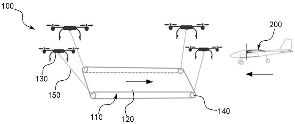
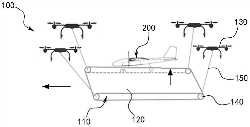
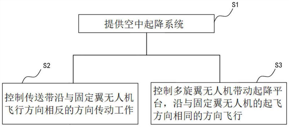
The invention provides an air take-off and landing system and an air take-off and landing method. The air take-off and landing system comprises a take-off and landing platform, a multi-rotor unmanned aerial vehicle and a control unit; the take-off and landing platform is provided with a conveying belt which serves as a take-off and landing runway of the fixed-wing; the multi-rotor unmanned aerial vehicle is connected to the take-off and landing platform; the control unit is connected to the conveying belt and the multi-rotor unmanned aerial vehicle and used for collecting position information of the fixed-wing unmanned aerial vehicle and controlling the conveying belt and the multi-rotor unmanned aerial vehicle according to the position information; the aerial take-off and landing system can make the fixed-wing unmanned aerial vehicle land by controlling the conveying belt to conduct transmission work in the direction opposite to the flying direction of the fixed-wing unmanned aerial vehicle, and can make the fixed-wing unmanned aerial vehicle take off by controlling the multi-rotor unmanned aerial vehicle to drive the take-off and landing platform to fly in the direction the same as the take-off direction of the fixed-wing unmanned aerial vehicle.

Description

technical field [0001] The invention relates to the technical field of unmanned aerial vehicles, in particular to an air take-off and landing system and an air take-off and landing method. Background technique [0002] The existing take-off and landing schemes for fixed-wing UAVs are mainly divided into two types, one is the conventional runway roll take-off and landing scheme, and the other is the combination of catapult takeoff and parachute drop. However, the runway roll takeoff and landing scheme has higher requirements on the takeoff and landing site, and requires a straight and long runway. Furthermore, the failure probability of the catapult-parachute combination scheme is higher than that of the runway roll-off and landing scheme, and it will cause damage to the fixed-wing UAV. In addition, the above two take-off and landing schemes for fixed-wing UAVs need to be completed on the ground, resulting in land occupation and the inability to achieve flexible transitions....

Claims


Application Information

Patent Timeline
Patent Type & Authority Applications(China)
IPC IPC(8): B64D5/00B64C27/08B64C39/02
CPCB64D5/00B64C27/08B64C39/02B64U10/10B64U80/82B64U2101/00
Inventor 郄新越
Owner BEIJING JINGDONG QIANSHITECHNOLOGY CO LTD
Learn More