While-drilling water plugging device for emergency rescue drilling

An emergency rescue, while drilling technology, which is applied to the drilling drive device in the wellbore, the valve device of the wellbore/well, and the drill pipe, etc., can solve the problem of low drilling efficiency, etc. Plugging effect, less time-consuming effect

Active Publication Date: 2021-12-21
CHINA UNIV OF GEOSCIENCES (BEIJING)
View PDF6 Cites 1 Cited by
  • Summary
  • Abstract
  • Description
  • Claims
  • Application Information

AI Technical Summary

Problems solved by technology

[0006] The purpose of the present invention is to provide a water plugging device for emergency rescue drilling while drilling to solve the technical problems in the prior art that air drilling needs to be switched to mud drilling and drilling efficiency is low when drilling into water-producing formations; The many technical effects that can be produced by the preferred technical solutions among the many technical solutions provided by the invention are described in detail below

Method used


Image

  • While-drilling water plugging device for emergency rescue drilling
  • While-drilling water plugging device for emergency rescue drilling
  • While-drilling water plugging device for emergency rescue drilling

Examples


Embodiment 1

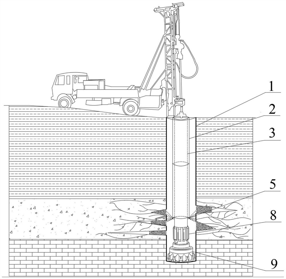
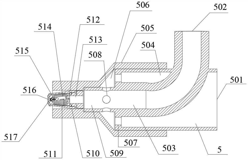
[0050] Such as Figure 1-Figure 7 As shown, this embodiment provides an emergency rescue drilling while drilling water plugging device, including a bypass assembly 6, a pneumatic nozzle 5 and a drill pipe with an inner cavity, wherein: see figure 1 As shown, the drill pipe is stretched into the well, and the drill pipe is connected with the air down-the-hole hammer 8, and the lower end of the air down-the-hole hammer 8 is connected with a drill bit 9. At least the upper part of the drill pipe is a double-walled drill pipe with an inner tube 3 and an outer tube 2, see figure 1 , the upper part of the drill pipe in this embodiment is a double-walled drill pipe, and the lower part is an ordinary single-walled drill pipe; an accommodating chamber 201 for storing the leakage sealing agent is formed between the inner pipe 3 and the outer pipe 2; the pneumatic nozzle 5 has uniform The liquid inlet 502 and the air inlet 501 are connected, and the liquid inlet 502 is connected with th...

specific Embodiment approach

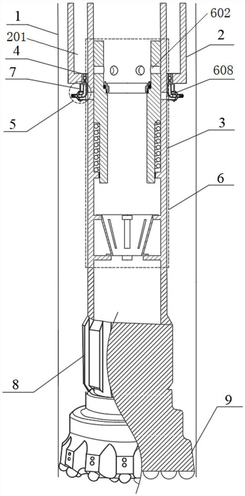
[0071] see figure 2 , Figure 5 and Figure 6 As shown, the bypass assembly 6 of this embodiment includes a lifting piston 605 and an elastic component, wherein: the lifting piston 605 is located in the inner cavity of the drill rod 604, the main flow channel 601 is formed in the lifting piston 605, and the bypass flow channel is arranged on the The bypass hole 602 on the peripheral wall of the lifting piston 605, the outer wall of the drill pipe 604 is provided with a communicating hole 608, and the communicating hole 608 communicates with the air inlet 501; the corresponding communicating hole 608 and the bypass hole 602 are located at the same On the vertical line, and the two are vertically staggered, and when the main channel 601 is blocked, the high-pressure airflow can push the lifting piston 605 to move downward and make the bypass hole 602 lead to the corresponding communication hole 608 Pass.

[0072] Such as Figure 5 and Figure 6 As shown, a plurality of bypas...

Embodiment 3

[0086] This embodiment is an improvement made on the basis of the above-mentioned embodiments. The drilling tool also includes a ball receiving mechanism 612. The ball receiving mechanism 612 is arranged in the inner cavity of the drill rod and is located below the bypass assembly 6 for receiving The valve opening ball and valve closing ball falling from the bypass assembly 6. The ball receiving mechanism 612 is located under the bypass assembly 6 and can receive the dropped valve opening and closing balls to ensure the smooth progress of the drilling work.

[0087] This embodiment provides a specific implementation of the ball receiving mechanism 612, see Figure 5 and Figure 7 As shown, the ball catching mechanism 612 of this embodiment includes a ball catching basket 619, which is used to receive the falling valve-opening balls and valve-closing balls; 620, the air can circulate through the grill hole 620;

[0088] The inner diameter of the ball receiving basket 619 dec...


PUM


Abstract

The invention provides a while-drilling water plugging device for emergency rescue drilling, relates to the field of drilling, and solves the problems that drilling needs to be switched and the drilling operation efficiency is low when a water outlet stratum is drilled. The device comprises a bypass assembly, a pneumatic spray head and a drill rod with an inner cavity, wherein at least the upper portion of the drill rod is a double-wall drill rod with an inner pipe and an outer pipe, and a containing cavity used for storing a plugging agent is formed between the inner pipe and the outer pipe; the pneumatic spray head is provided with a liquid inlet and an air inlet which communicate with each other, and the liquid inlet can communicate with the containing cavity; the bypass assembly is provided with a main flow channel and a bypass flow channel, the main flow channel communicates with the inner cavity, and the bypass flow channel is blocked from the air inlet; and when the main flow channel is blocked, the bypass flow channel communicates with the air inlet, and air can enter the pneumatic spray head to be mixed with the plugging agent and then is sprayed out. The device can be used for plugging while drilling, a large amount of water is prevented from flowing into a drill hole from a water outlet stratum, a large amount of time consumed by switching materials back and forth during traditional air drilling plugging is avoided, and the requirements for rapidness, accuracy and safety of emergency rescue are met.

Description

technical field [0001] The invention relates to the technical field of emergency rescue drilling for mine accidents, in particular to a water blocking device for emergency rescue drilling while drilling. Background technique [0002] Mine accident emergency rescue is an important part of mine safety production work, which has been widely concerned and highly valued by the society. Once a mining disaster occurs, it is very easy to cause roadway blockage, miners are trapped underground, communication channels are interrupted, rescue channels are blocked, and rescuers cannot approach to carry out rescue. In the rescue of mine accidents in recent years, in addition to the traditional methods such as excavating winding lanes and digging connecting lanes, the rapid drilling rescue technology on the ground has been used to drill to the trapped miners in the disaster area and form an effective connected borehole to communicate with the trapped miners in the disaster area. Establish...

Claims


Application Information

Patent Timeline
Patent Type & Authority Applications(China)
IPC IPC(8): E21B4/14E21B33/13E21B17/18E21B34/14
CPCE21B4/14E21B33/13E21B17/18E21B34/142
Inventor 刘永升孟庆生周兢豆子钧阳志远杨甘生云霄
Owner CHINA UNIV OF GEOSCIENCES (BEIJING)
Why Eureka
Try Eureka