Water decanter

A decanter and water decanter technology, applied in water/sewage treatment, chemical instruments and methods, biological water/sewage treatment, etc., can solve the problems of poor sewage treatment effect of decanters, achieve good sewage treatment effect, Precise effect of control of stop drain signal

Inactive Publication Date: 2016-09-14
HUAYI ENVIRONMENTAL PROTECTION CO LTD
View PDF6 Cites 1 Cited by
  • Summary
  • Abstract
  • Description
  • Claims
  • Application Information

AI Technical Summary

Problems solved by technology

[0004] Therefore, the technical problem to be solved by the present invention is to overcome the disadvantages of the prior art that the decanter has poor sewage treatment effect, so as to provide a decanter with better water treatment effect and more efficient

Method used


Image

  • Water decanter

Examples


Embodiment 1

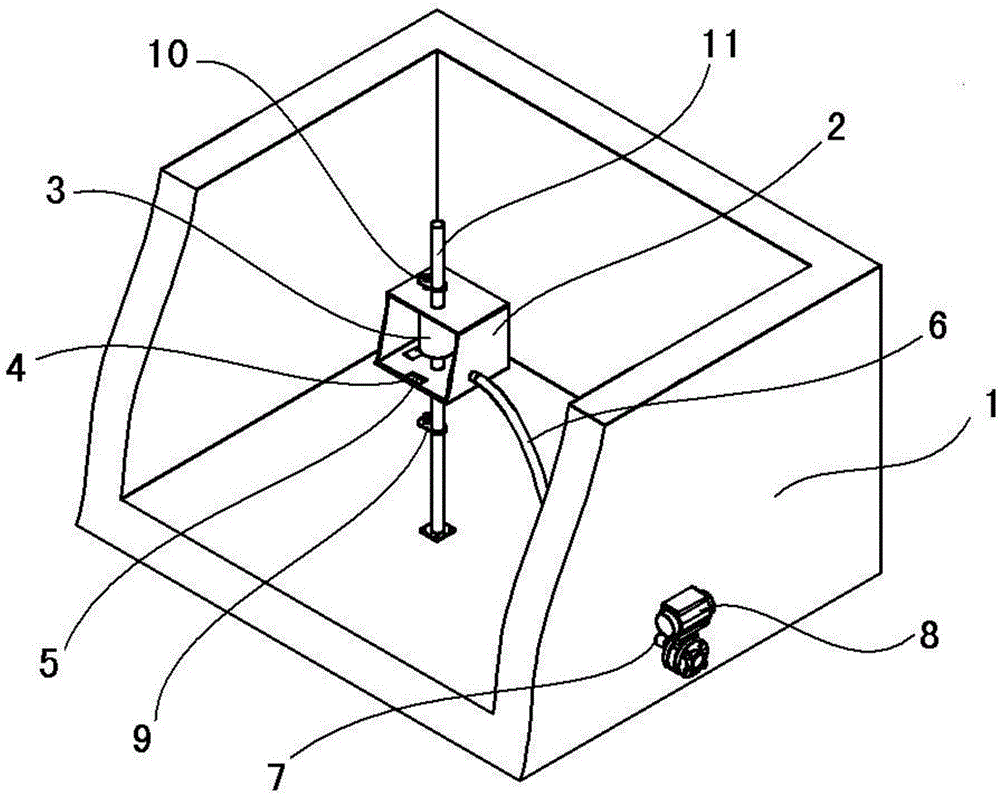
[0041] figure 1 It is a structural schematic diagram of a water decanter placed in a sewage treatment tank with a partial perspective of the weir housing provided in Embodiment 1 of the present invention. Such as figure 1 As shown, the decanter provided in this embodiment includes: a decanting structure floating on the surface of the pool, and the decanting structure has a water collection area; a drain hose 6, one end communicates with the water collection area, and the other end It communicates with the drain port 7 on the pool wall, and a drain valve 8 is set on the decanting structure and / or the pool wall to control the drainage of the drain hose 6 or to close the drain; the downstroke switch 9 is fixedly installed in the pool and located on the On the moving path of the decanting structure as the liquid level drops, the downstroke switch 9 is electrically connected to the drain valve 8, and is triggered by the decanting structure when the liquid level drops and moves to ...

Embodiment 2

[0059] This embodiment provides a decanter as an alternative to the first embodiment. The difference between the decanter and the first embodiment is:

[0060] In the decanting structure of this embodiment, the float is arranged above the water collection weir, and the outer surface of the float and the upper surface of the water collection weir are provided with multiple sets of corresponding fixing rings. The water collecting weir is connected with the water collecting weir through the connecting chain arranged between each set of the fixing rings, so that the water collecting weir can float on the liquid surface along with the float.

Embodiment 3

[0062] This embodiment provides a decanter as an alternative to the first embodiment. The difference between the decanter and the first embodiment is:

[0063] The guide rail structure of this embodiment includes a plurality of guide columns arranged circumferentially around the decanting structure, the guide columns are arranged perpendicular to the bottom of the pool, and the shell surface of the water collection weir is correspondingly provided with a plurality of traction columns. The end of each traction chain is connected with a fixed ring, and the fixed ring is slidably sleeved on the guide column, so that the water collecting weir can be pulled by the traction chain and rise and fall with the liquid level. Move up and down along the axis of the guide column.

[0064] Both the upstroke switch and the downstroke switch are fixed on the moving path of the decanting structure along with the liquid level through a horizontal bracket parallel to the bottom of the pool.


PUM


Abstract

A water decanter comprises a decanting structure, which floats on a tank and comprises a water collecting area; a water discharge soft pipe, wherein one end of the water discharge soft pipe is communicated with the water collecting area, the other end is communicated with a water outlet in the tank wall, and the decanting structure and/or the tank wall is provided with a water discharge valve, which can control the water discharge soft pipe to start/stop water discharging; and a down stroke switch, which is fixedly arranged in the tank and is in the moving route of decanting structure, wherein the decanting structure descends along the moving route as the water level goes down, and the down stroke switch is electrically connected to the water discharge valve. When the water level goes to a position that indicates the water discharging should be stopped, the decanting structure is triggered to control the water discharge valve to close the water discharge soft pipe so as to stop water discharging. The provided water decanter has the advantages that the whole process is automatic, the control is precise, the processing is efficient, the structure is simple, the cost is low, and thus the water decanter is worthy to popularize and use.

Description

technical field [0001] The invention relates to the technical field of sewage treatment, in particular to a decanter. Background technique [0002] The decanter is a necessary mechanical device for the intermittent activated sludge process to treat sewage. At present, the non-powered buoy type decanter is widely used because of its simple structure, energy saving and environmental protection, and convenient decanting. The sewage treatment mechanism is the same as the ordinary activated sludge method, the difference is that the raw sewage does not flow through each treatment unit in sequence, but is discharged into a single reaction tank, and the operations for different purposes are realized in chronological order. The basic operating procedures mainly include water inflow , aeration, static, drainage these four basic processes. The sewage is discharged into the reaction tank containing activated sludge. When a certain water storage capacity is reached, the water intake is ...

Claims


Application Information

Patent Timeline
Patent Type & Authority Applications(China)
IPC IPC(8): C02F3/12C02F3/00
CPCC02F3/00C02F3/1263C02F2201/002C02F2203/00Y02W10/10
Inventor 朱伟杰杨侃李龙斌陈恒龙
Owner HUAYI ENVIRONMENTAL PROTECTION CO LTD
Why Eureka
Try Eureka