Portable optical measuring instrument
An optical measurement and portable technology, applied in the field of measuring instruments, can solve the problems of inconvenience to carry and cannot be reduced in size, and achieve the effects of improved portability, simple structure and reasonable design
- Summary
- Abstract
- Description
- Claims
- Application Information
AI Technical Summary
Problems solved by technology
Method used
Image

Examples
Embodiment Construction
[0023] In order to make the object, technical solution and advantages of the present invention clearer, the present invention will be further described in detail below in conjunction with the accompanying drawings and embodiments. It should be understood that the specific embodiments described here are only used to explain the present invention, not to limit the present invention.
[0024] The specific implementation of the present invention will be described in detail below in conjunction with specific embodiments.
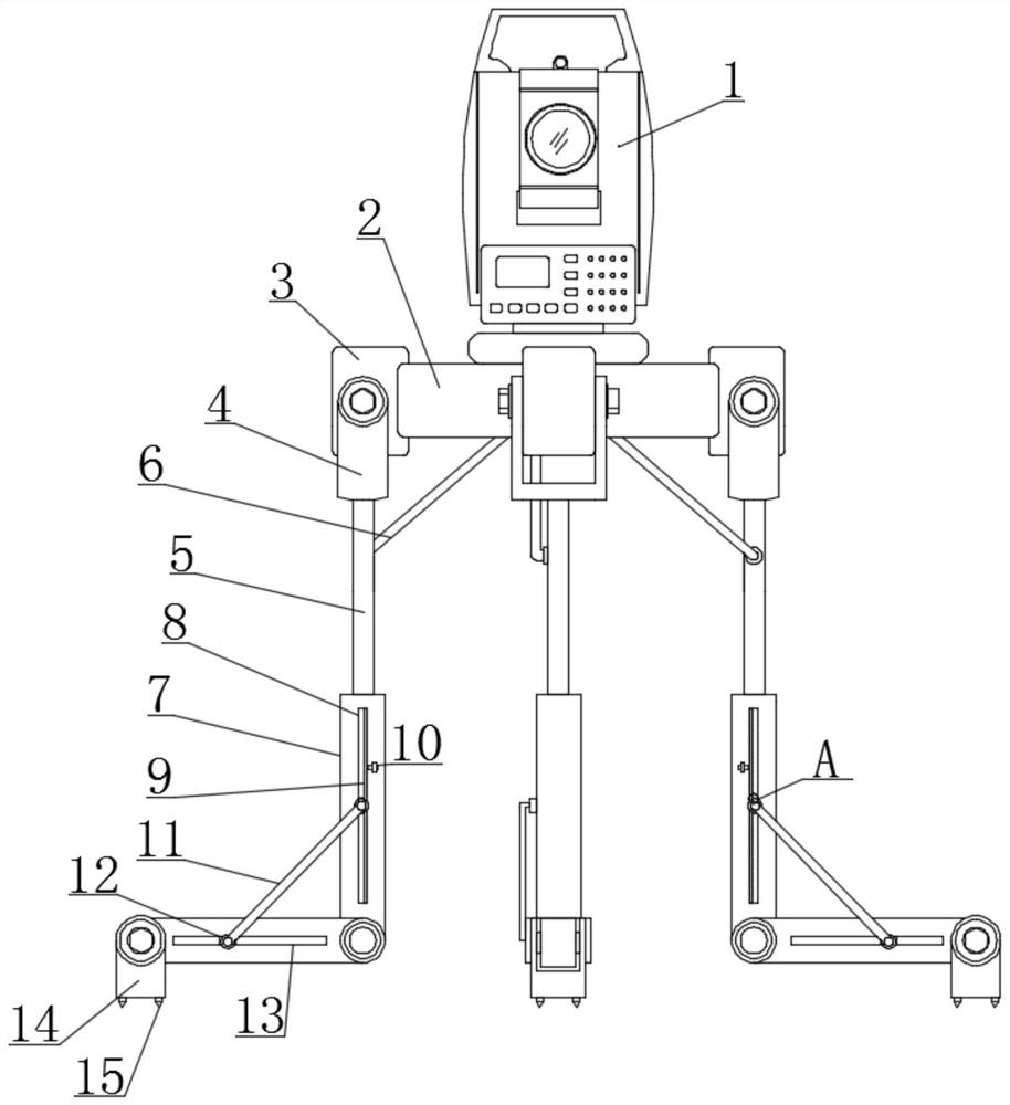
[0025] Such as figure 1 As shown, it is a schematic structural diagram of a portable optical measuring instrument provided by an embodiment of the present invention, including an optical measuring instrument main body 1, and the portable optical measuring instrument also includes:
[0026] Install the adjustment seat 2 for installing the main body 1 of the optical measuring instrument;
[0027] A telescopic support structure, the telescopic support structure is...
PUM
 Abstract
Description
Claims
Application Information
 - R&D
- Intellectual Property
- Life Sciences
- Materials
- Tech Scout
- Unparalleled Data Quality
- Higher Quality Content
- 60% Fewer Hallucinations
Browse by: Latest US Patents, China's latest patents, Technical Efficacy Thesaurus, Application Domain, Technology Topic, Popular Technical Reports.
© 2025 PatSnap. All rights reserved.Legal|Privacy policy|Modern Slavery Act Transparency Statement|Sitemap|About US| Contact US: help@patsnap.com