Methods of forming microelectronic devices, and related microelectronic devices and electronic systems

A microelectronic device, semi-conductive technology, applied in the direction of circuits, capacitors, electrical components, etc., can solve problems such as defects, hindering memory devices, etc.

Pending Publication Date: 2021-12-21
MICRON TECH INC
View PDF5 Cites 0 Cited by
  • Summary
  • Abstract
  • Description
  • Claims
  • Application Information

AI Technical Summary

Problems solved by technology

However, the processing conditions (e.g., temperature, pressure, materials) used to form memory arrays above the substrate control logic structure can limit the configuration and performance of control logic devices within the substrate control logic structure
In addition, the number, size, and arrangement of different control logic devices employed within the base control logic structure can also undesirably prevent memory device size (e.g., horizontal footprint) reduction and / or memory device performance improvements (e.g., faster memory cell turn-on / turn-off speed, lower threshold switching voltage requirements, faster data transfer rates, lower power consumption)

Method used


Image

  • Methods of forming microelectronic devices, and related microelectronic devices and electronic systems
  • Methods of forming microelectronic devices, and related microelectronic devices and electronic systems
  • Methods of forming microelectronic devices, and related microelectronic devices and electronic systems

Examples


Embodiment 1

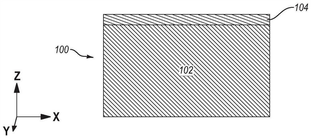
[0101] Embodiment 1: A method of forming a microelectronic device, which includes: forming a microelectronic device structure, the microelectronic device structure includes: a base structure; a doped semiconductive structure, which includes a first layer overlying the base structure a portion and a second portion extending vertically from the first portion into the base structure; a stack structure overlying the doped semiconducting structure and comprising a vertically alternating sequence of conductive structures and insulating structures; a cell pillar structure, extending vertically through the stack structure to the first portion of the doped semiconducting structure; and a digit line structure vertically overlying the stack structure; forming additional microelectronic device structures including control logic; attaching the microelectronic device structure to the additional microelectronic device structure to form a microelectronic device structure assembly, the digit li...

Embodiment 2

[0102] Embodiment 2: The method of Embodiment 1, wherein forming a microelectronic device structure comprises forming the microelectronic device further comprising a conductive contact structure extending vertically through the stacked structure into the doped semiconducting structure structure.

Embodiment 3

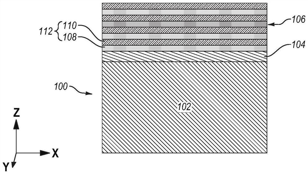
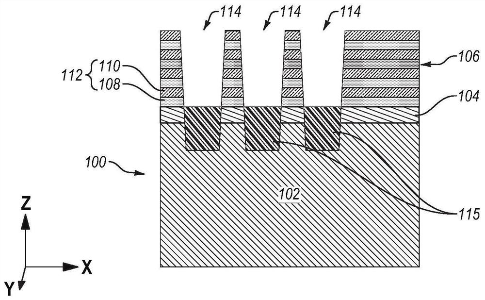
[0103] Embodiment 3: The method of any one of embodiments 1 and 2, wherein forming the microelectronic device structure comprises: forming a preliminary stack structure on a doped semiconducting material overlying the base structure, wherein The preliminary stack structure includes a vertical alternating sequence of first insulating structures and second insulating structures; forming an opening extending vertically through the preliminary stack structure and the doped semiconductive material into the base structure; using additional semiconductive material filling a lower portion of the opening positioned within the base structure and the doped semiconducting material; annealing the doped semiconducting material and the additional semiconducting material to form the doped semiconducting material therefrom structure; forming the unit pillar structure in the remaining upper portion of the opening; forming a slot extending through the preliminary stack structure; using the slot t...


PUM


Abstract

The invention relates to methods of forming microelectronic devices, and related microelectronic devices and electronic systems. The method of forming a microelectronic device comprises forming a microelectronic device structure comprising a base structure, a doped semiconductive structure comprising a first portion overlying the base structure and second portions vertically extending from the first portion and into the base structure, a stack structure overlying the doped semiconductive structure, cell pillar structures vertically extending through the stack structure and to the doped semiconductive structure, and digit line structures vertically overlying the stack structure. An additional microelectronic device structure comprising control logic devices is formed. The microelectronic device structure is attached to the additional microelectronic device structure to form a microelectronic device structure assembly. The carrier structure and the second portions of the doped semiconductive structure are removed. The first portion of the doped semiconductive structure is then patterned to form at least one source structure coupled to the cell pillar structures. Devices and systems are also described.

Description

[0001] Cross References to Related Applications [0002] This application claims that the serial number of the application titled "METHODS OF FORMING MICROELECTRONIC DEVICES, AND RELATED MICROELECTRONIC DEVICES AND ELECTRONIC SYSTEMS" filed on June 18, 2020 is 16 / 905,747 US patent application relating to a titled "Microelectronics" filed June 18, 2020 listing Kunal R. Parekh as inventor US Patent Application Serial No. 16 / 905,385 for Electronic Devices and Related Methods, Memory Devices, and Electronic Systems (MICROELECTRONIC DEVICES, AND RELATED METHODS, MEMORY DEVICES, AND ELECTRONIC SYSTEMS). This application is also related to the application titled "Methods of Forming Microelectronic Devices and Related Microelectronic Devices, Memory Devices, Electronic Systems, and Additional Methods," filed on June 18, 2020, listing Kunal R. Parekh as the inventor. (METHODS OF FORMING MICROELECTRONIC DEVICES, ANDRELATED MICROELECTRONIC DEVICES, MEMORY DEVICES, ELECTRONIC SYSTEMS, AN...

Claims


Application Information

Patent Timeline
IPC IPC(8): H01L27/11529H01L27/11556H01L27/11548H01L27/11531
CPCH10B41/42H10B41/41H10B41/50H10B41/27H01L28/60H01L25/18H01L2224/08145H01L24/80H01L24/08H01L2224/80895H01L2224/80896H01L2224/80357H01L2224/09181H10B43/40H10B43/27H01L2224/05647H01L2224/80379H01L2224/056H01L2224/05686H01L2224/05638H01L2224/05684H01L2224/05624H01L2224/05567H01L2924/00014H01L2924/045H01L2924/047H01L2924/059H01L2924/0464H01L2924/01014H01L2924/0504H01L2924/05042H01L2924/0549H01L2924/0544H01L2924/0543H01L2924/01005H01L2924/053H01L2924/01015H01L2924/01009H01L2924/0535H01L2924/01041H01L2924/013H01L2924/049H01L2924/01006H01L2924/0534H01L2924/01072H01L2924/01013H01L2924/05442H01L2924/01022H01L25/0657H01L25/50H01L2924/19041H01L2924/1431H01L2924/14511H01L2924/19104H01L2225/06524
Inventor K·R·帕雷克
Owner MICRON TECH INC
Why Eureka
Try Eureka