
Moving bed adsorption tower and flue gas purification system with same

An adsorption tower and moving bed technology, applied in gas treatment, chemical instruments and methods, dispersed particle separation, etc., can solve the problems of affecting adsorption efficiency, improving operation difficulty, uneven adsorption, etc., and achieving uniform blanking speed and adsorption effect. uniform effect

Active Publication Date: 2021-12-24
CHINA HUANENG GRP CO LTD +1
View PDF4 Cites 1 Cited by
  • Summary
  • Abstract
  • Description
  • Claims
  • Application Information

AI Technical Summary

Problems solved by technology

In the field of flue gas purification, fixed bed adsorption towers are usually used to adsorb pollutants in flue gas to achieve the purpose of purifying flue gas. Inhomogeneity, poor adsorption effect, and the reduction of adsorption capacity with the extension of use time, and the need to stop working when the adsorbent needs to be replaced, which seriously affects the adsorption efficiency and increases the difficulty of operation
The related technology adopts the moving bed adsorption tower to make the adsorbent flow in the tower, which overcomes the problem that the adsorption capacity of the fixed bed adsorption tower decreases with the prolongation of use time, but there are still uneven distribution of flue gas and poor purification effect in the moving bed adsorption tower. ideal question

Method used


Image

  • Moving bed adsorption tower and flue gas purification system with same
  • Moving bed adsorption tower and flue gas purification system with same
  • Moving bed adsorption tower and flue gas purification system with same

Examples


Embodiment Construction

[0032] Embodiments of the invention are described in detail below, examples of which are illustrated in the accompanying drawings. The embodiments described below by referring to the figures are exemplary and are intended to explain the present invention and should not be construed as limiting the present invention.

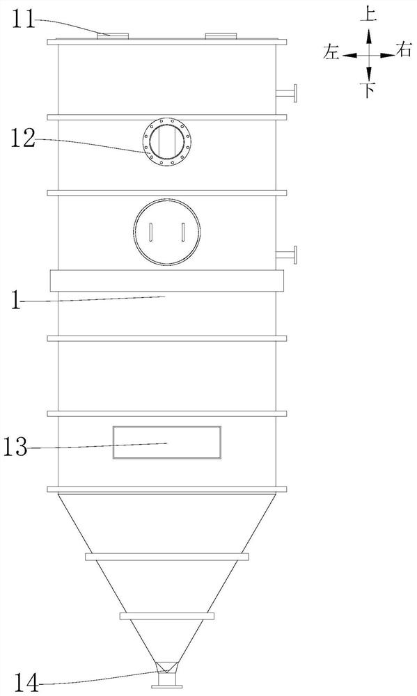
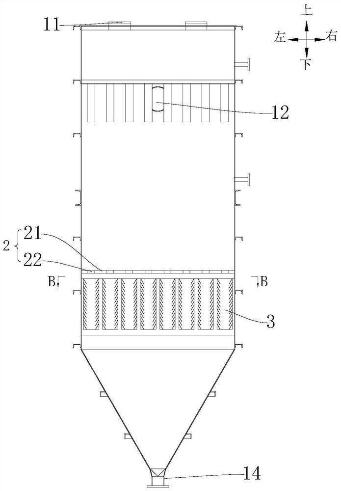
[0033] Such as Figure 1 to Figure 6 As shown, the moving bed adsorption tower according to the embodiment of the present invention includes a tower body 1 , a distributor 2 and a plurality of downcomers 3 .

[0034] There is a cavity in the tower body 1, and the tower body 1 is provided with a feed port 11, a discharge port 14, a flue gas inlet 13 and a flue gas outlet 12 communicating with the cavity, and the cavity includes a packing section filled with an adsorbent;

[0035] Specifically, the feeding port 11 is located at the upper end of the tower body 1, the discharge port 14 is located at the lower end of the tower body 1, the flue gas inlet 13 is located...


PUM

PropertyMeasurementUnit
Widthaaaaaaaaaa
Lengthaaaaaaaaaa

Abstract

The invention discloses a moving bed adsorption tower and a flue gas purification system with the same. The moving bed adsorption tower comprises a tower body, a distributor and a plurality of blanking pipes, the tower body is internally provided with a cavity, the tower body is provided with a flue gas inlet and a flue gas outlet which are communicated with the cavity, and the cavity comprises a filler section filled with an adsorbent; the distributor is arranged in the tower body, is provided with a plurality of blanking ports, and is positioned below the filler section, so that the adsorbent in the filler section flows out through the blanking ports; and the plurality of blanking pipes are in one-to-one correspondence with the plurality of blanking ports, the blanking pipes are positioned below the corresponding blanking ports, and the flue gas inlets are positioned below the blanking ports. At least part of the side wall of the blanking pipes is of a hollow structure, the side wall comprises a plurality of grid bars arranged at intervals in the length direction of the blanking pipe, a smoke channel allowing smoke to circulate is formed between every two adjacent grid bars, and the grid bars incline inwards and downwards, so that the bottom ends of the grid bars can be located on the inner sides of the top ends of the grid bars. The moving bed adsorption tower has the advantages of uniform adsorption and good adsorption effect.

Description

technical field [0001] The present application relates to the technical field of flue gas treatment, in particular to a moving bed adsorption tower and a flue gas purification system with a moving bed adsorption tower. Background technique [0002] The large amount of pollutants produced by coal combustion flue gas is one of the important factors that endanger the atmospheric environment and human health. In the field of flue gas purification, fixed bed adsorption towers are usually used to adsorb pollutants in flue gas to achieve the purpose of purifying flue gas. The problem of unevenness, poor adsorption effect, and the decrease of adsorption capacity with the extension of use time, and the need to stop working when the adsorbent needs to be replaced, seriously affects the adsorption efficiency and increases the difficulty of operation. The related technology adopts the moving bed adsorption tower to make the adsorbent flow in the tower, which overcomes the problem that ...

Claims


Application Information

Patent Timeline
IPC IPC(8): B01D53/08
CPCB01D53/08B01D2258/0283Y02A50/20
Inventor 汪世清许世森郜时旺肖平刘练波牛红伟黄斌雷中辉张再明
Owner CHINA HUANENG GRP CO LTD
Features
  • Generate Ideas
  • Intellectual Property
  • Life Sciences
  • Materials
  • Tech Scout
  • Unparalleled Data Quality
  • Higher Quality Content
  • 60% Fewer Hallucinations
Learn More