
Honeycomb ceramic carrier for vehicle

A technology for honeycomb ceramic carrier and vehicle, which is applied in the direction of catalyst carrier, organic compound/hydride/coordination complex catalyst, dispersed particle separation, etc. To achieve good catalytic reaction effect, good catalytic effect, and improve the overall utilization rate

Pending Publication Date: 2021-12-24
TAIZHOU THREE WAY VEHICLE CATALYTIC CONVERTER CO LTD
View PDF0 Cites 0 Cited by
  • Summary
  • Abstract
  • Description
  • Claims
  • Application Information

AI Technical Summary

Problems solved by technology

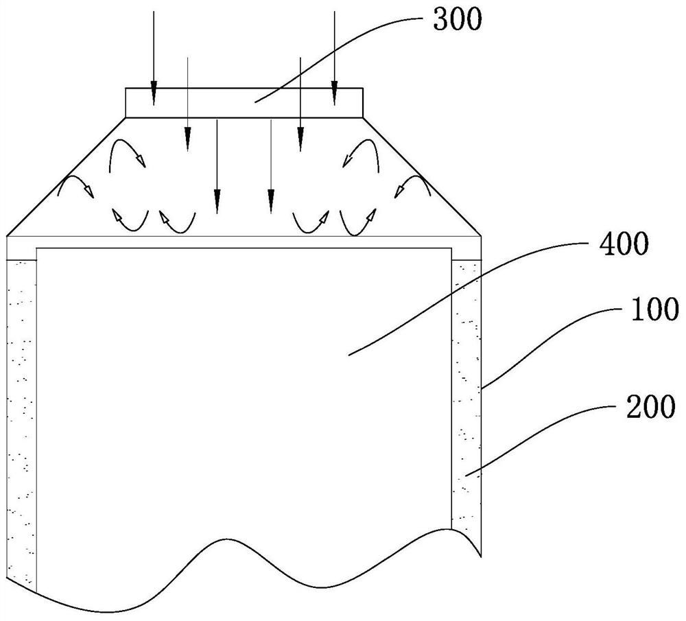
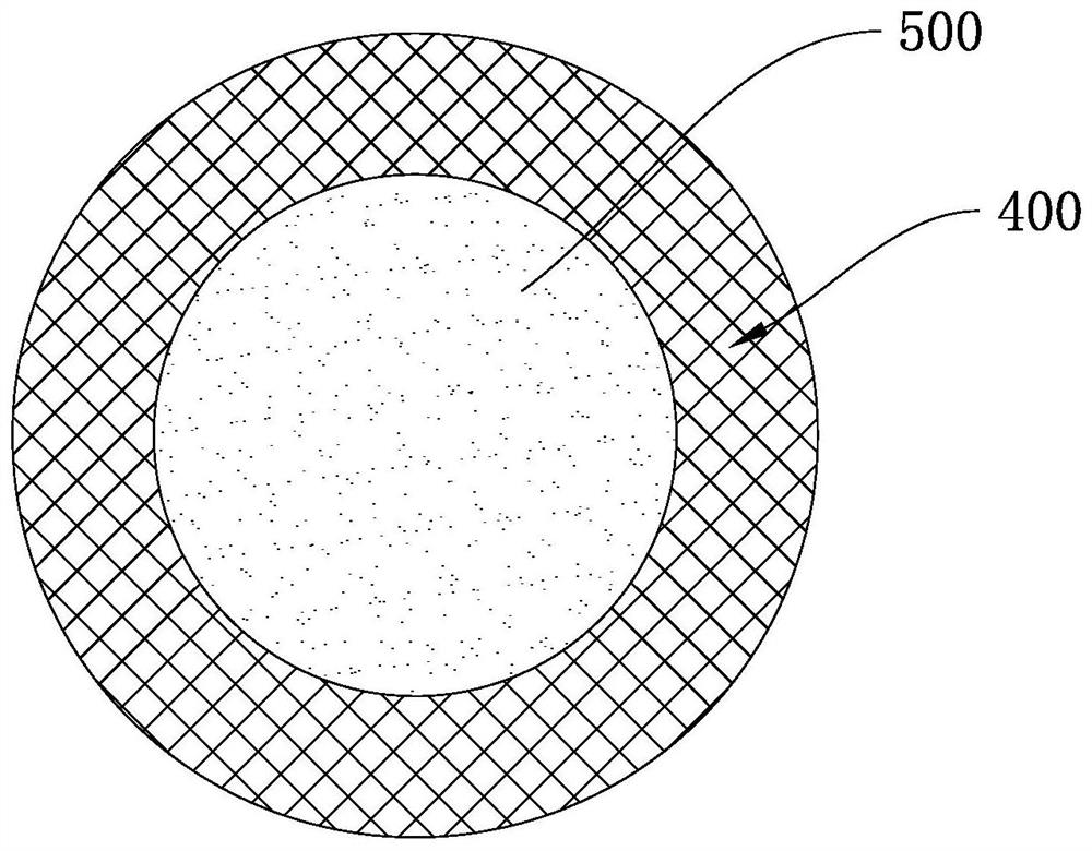
[0003] Most of the pores of the honeycomb carrier in the prior art are evenly distributed. figure 1 and figure 2 As shown, the cylinder body 100 is lined with a liner 200, the carrier 400 is installed in the liner 200, and the cylinder body 100 is provided with a gas inlet 300. After the gas flows into the cylinder body 100, the gas flow distribution is that a large amount of gas gathers on the carrier 400 The central part of the carrier 400, and the state of less ventilation in the peripheral pores of the carrier 400, will cause the catalyst reaction load in the central part of the carrier 400 to be too high, a large amount of heat accumulation and long-term high-speed airflow erosion, which will easily lead to premature deactivation and thermal weakening of the catalyst, and even The case where the carrier 400 is thermally fused, that is, figure 2 The heat melting area 500 appears in the middle of the carrier 400 as shown
[0004] Therefore, in view of the problem that the uniform distribution of carrier pores in the prior art leads to the low utilization rate of the catalyst, it is urgent to propose a new carrier structure.

Method used


Image

  • Honeycomb ceramic carrier for vehicle
  • Honeycomb ceramic carrier for vehicle
  • Honeycomb ceramic carrier for vehicle

Examples


Embodiment 1

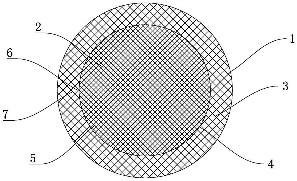
[0028] This embodiment provides a kind of honeycomb ceramic carrier for vehicles, combined with image 3 with Figure 4 As shown, it includes a carrier body 1, and the carrier body 1 is provided with a high-density hole area 2 near the center and a low-density hole area 3 near the edge, and the number of channels 5 per unit area in the high-density hole area 2 is The number is higher than the number of channels 5 per unit area in the low-density hole area 3, and the high-density hole area 2 and the low-density hole area 3 are separated by the transition wall 4. Wherein, the high-density hole region 2 has 900 holes 5 per square inch, the low-density hole region 3 has 400 holes 5 per square inch, and the transition wall 4 has a wall thickness of 0.1 mm.

[0029] In the present invention, when in use, more gas is catalyzed and discharged through the high-density pore region 2 , and less gas is catalyzed and discharged through the low-density pore region 3 . Therefore, the pres...

Embodiment 2

[0036] This embodiment provides a kind of honeycomb ceramic carrier for vehicles, combined with image 3 with Figure 4 As shown, it includes a carrier body 1, and the carrier body 1 is provided with a high-density hole area 2 near the center and a low-density hole area 3 near the edge, and the number of channels 5 per unit area in the high-density hole area 2 is The number is higher than the number of channels 5 per unit area in the low-density hole area 3, and the high-density hole area 2 and the low-density hole area 3 are separated by the transition wall 4. Wherein, the high-density hole area 2 has 1200 holes 5 per square inch, the low-density hole region 3 has 600 holes 5 per square inch, and the transition wall 4 has a wall thickness of 0.15 mm.

[0037] In the present invention, when in use, more gas is catalyzed and discharged through the high-density pore region 2 , and less gas is catalyzed and discharged through the low-density pore region 3 . Therefore, the pres...

Embodiment 3

[0044] This embodiment provides a kind of honeycomb ceramic carrier for vehicles, combined with image 3 with Figure 4 As shown, it includes a carrier body 1, and the carrier body 1 is provided with a high-density hole area 2 near the center and a low-density hole area 3 near the edge, and the number of channels 5 per unit area in the high-density hole area 2 is The number is higher than the number of channels 5 per unit area in the low-density hole area 3, and the high-density hole area 2 and the low-density hole area 3 are separated by the transition wall 4. Wherein, the area of ​​the high-density hole region 2 has 1050 holes 5 per square inch, the area of ​​the low-density hole region 3 has 500 holes 5 per square inch, and the wall thickness of the transition wall 4 is 0.12 mm.

[0045] In the present invention, when in use, more gas is catalyzed and discharged through the high-density pore region 2 , and less gas is catalyzed and discharged through the low-density pore ...


PUM

PropertyMeasurementUnit
thicknessaaaaaaaaaa

Abstract

The invention belongs to the technical field of automobile exhaust treatment, and particularly relates to a honeycomb ceramic carrier for a vehicle. Aiming at the problem of low overall utilization rate of a catalyst caused by uniform distribution of carrier pore channels in the prior art, the invention provides the honeycomb ceramic carrier for the vehicle, the carrier comprises a carrier body, and a high-density pore area close to the central position and a low-density pore area close to the edge position are arranged in the carrier body. The number of pore channels in the unit area of the high-density pore area is larger than that of pore channels in the unit area of the low-density pore area, and the high-density pore area and the low-density pore area are isolated through a transition wall. The interior of the carrier body is divided into the high-density pore area close to the center position and the low-density pore area close to the edge position by the transition wall, so that more catalysts can be loaded at the center position compared with the edge position, the distribution mode of airflow is better met, and the overall utilization rate of the catalysts is improved.

Description

technical field [0001] The invention belongs to the technical field of automobile tail gas treatment, and in particular relates to a honeycomb ceramic carrier for automobiles. Background technique [0002] The three-way catalytic converter is the main core device of automobile exhaust after-treatment technology. When the harmful gas in the engine exhaust passes through the three-way catalytic converter, it will undergo oxidation and reduction reactions with the active coating on the honeycomb carrier channel, and the harmful CO, HC , NO x Converted to non-toxic CO 2 , N 2 and H 2 O. [0003] Most of the pores of the honeycomb carrier in the prior art are evenly distributed. figure 1 with figure 2 As shown, the cylinder body 100 is lined with a liner 200, the carrier 400 is installed in the liner 200, and the cylinder body 100 is provided with a gas inlet 300. After the gas flows into the cylinder body 100, the gas flow distribution is that a large amount of gas gather...

Claims


Application Information

Patent Timeline
Patent Type & Authority Applications(China)
IPC IPC(8): B01J31/38B01J32/00B01D53/94B01D53/62B01D53/72B01D53/56
CPCB01J31/38B01D53/945Y02A50/20
Inventor 王六杞
Owner TAIZHOU THREE WAY VEHICLE CATALYTIC CONVERTER CO LTD
Learn More