Supercharge Your Innovation With Domain-Expert AI Agents!

Shearing device based on industrial vision and shearing method thereof

A shearing device and visual technology, applied in the field of automation, can solve the problems of large workpiece allowance, inconvenient secondary processing of workpieces, etc., and achieve the effects of good finished product effect, improved precision value, and prevention of deflection.

Inactive Publication Date: 2021-12-24
南京丰耀科技有限公司
View PDF0 Cites 0 Cited by
  • Summary
  • Abstract
  • Description
  • Claims
  • Application Information

AI Technical Summary

Problems solved by technology

[0002] The final molding of many workpieces often requires multiple processing steps, especially for some workpieces with curved surfaces, either to process the workpiece with a margin on the original material, or to bend the workpiece after processing. A kind of processing procedure is often the priority procedure. This kind of raw material is usually a continuous line segment extending in a fixed direction in advance. The continuous line segment is stretched along the vertical direction of its fixed direction to form a continuous curved surface. The continuous curved surface is often the original workpiece. On the upper or lower surface of the original material, a number of required workpieces are processed. The processed workpieces often need to be processed twice or three times to complete the final shape. Some special workpieces need to be left in the shape of the surface. There is a margin for multiple processing, and a certain margin needs to be left on the edge surface or the edge surface with a certain thickness. When a certain angle needs to be left relative to the straight line between the upper and lower surfaces, the conventional shearing device is not suitable. No matter how applicable, one is that the workpiece allowance after processing is too large, which is not convenient for the secondary processing of the workpiece; the other is that conventional shearing devices often use knives, which are suitable for processing in straight lines. For curves and further curve edges The side with a certain thickness cannot be processed well

Method used


Image

  • Shearing device based on industrial vision and shearing method thereof
  • Shearing device based on industrial vision and shearing method thereof
  • Shearing device based on industrial vision and shearing method thereof

Examples


Embodiment Construction

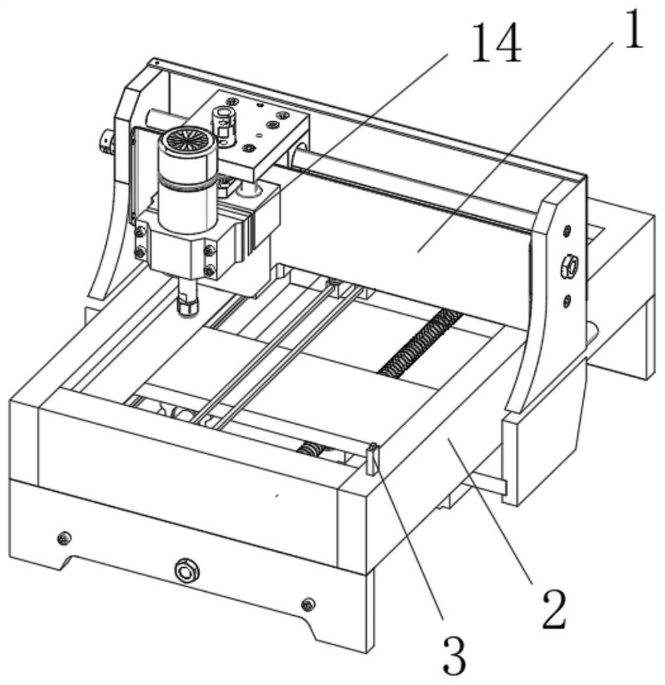
[0059] When using materials to cut workpieces, the conventional process often requires multiple shears, leaving a preset shear allowance each time to facilitate the next processing. This type of process is more troublesome and the process is more complicated. Especially for workpieces with a certain thickness, the thickness surface may be required to be provided with a specified inclined surface. Conventional shearing devices are often linear and are not suitable for this type of shearing process.

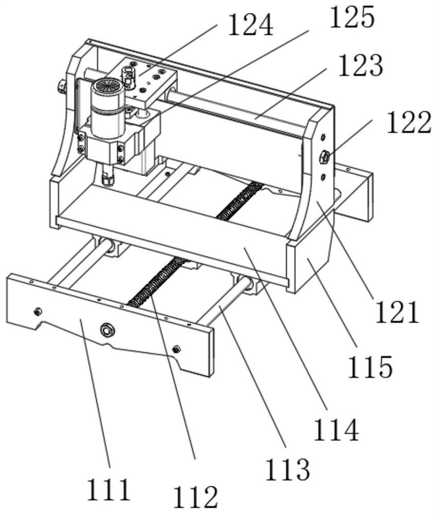
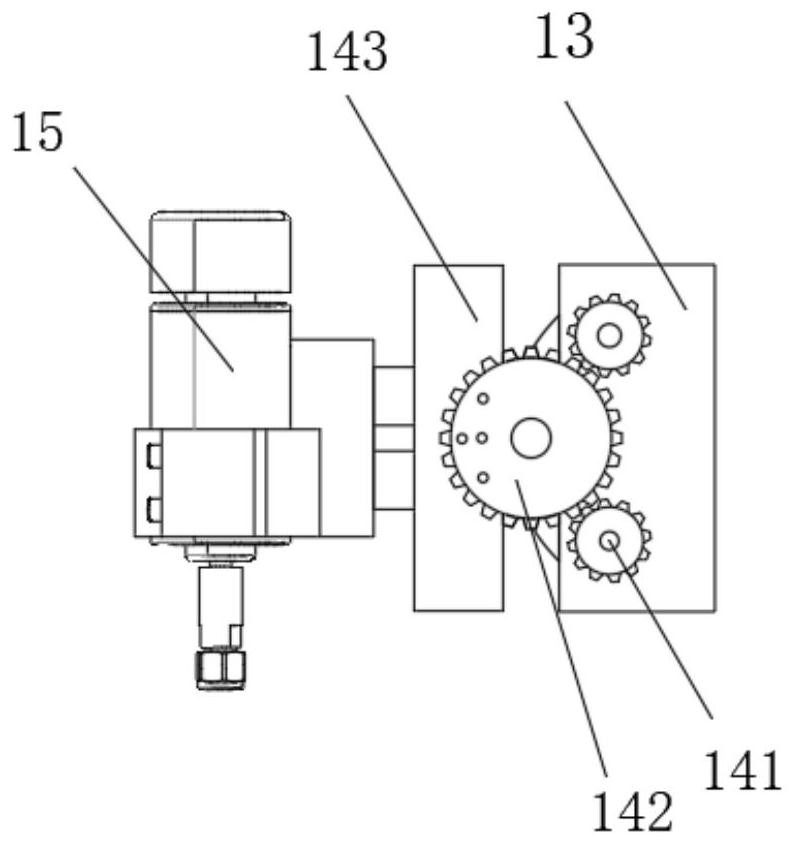
[0060] The shearing device in this embodiment preferably uses the laser component 15 to carry out customized or preset graphic cutting of the original material, and enters the three-dimensional facial spectrum data of the required image and the three-dimensional facial spectrum data of the original material to the image acquisition center, and The original material is fixed at a preset position on the positioning module 2, wherein the positioning module 2 is installed on the base of...


PUM


Abstract

The invention discloses a shearing device based on industrial vision and a shearing method thereof, and belongs to the technical field of automation. The shearing device comprises a movable shearing module, a positioning module and a visual calculation module, wherein the movable shearing module is used for controlling movement of a laser assembly in the spatial position and controlling movement and local deflection of the laser assembly in the space, the positioning module is installed on a base of the movable shearing module, and the visual calculation module is arranged on a mounting seat of the positioning module and is used for calculating an angle difference between an original material and a theoretical material when the original material is positioned and determining a shearing path of the laser component. According to the shearing device, the shearing device is used for processing a required workpiece from the material, the laser assembly is used for shearing, the finished product effect is better, a sight distance measuring instrument and a calculation center are used for calculating the angle difference between actual positioning and theoretical positioning of the material, the deflection angle of the laser assembly is regulated and controlled, and the accurate value of workpiece shearing is further increased.

Description

technical field [0001] The invention belongs to the technical field of automation, in particular to an industrial vision-based cutting device and a cutting method thereof. Background technique [0002] The final molding of many workpieces often requires multiple processing steps, especially for some workpieces with curved surfaces, either to process the workpiece with a margin on the original material, or to bend the workpiece after processing. A kind of processing procedure is often the priority procedure. This kind of raw material is usually a continuous line segment extending in a fixed direction in advance. The continuous line segment is stretched along the vertical direction of its fixed direction to form a continuous curved surface. The continuous curved surface is often the original workpiece. On the upper or lower surface of the original material, a number of required workpieces are processed. The processed workpieces often need to be processed twice or three times t...

Claims


Application Information

Patent Timeline
IPC IPC(8): B23K26/04B23K26/02B23K26/03B23K26/08B23K26/38B23K26/70B23K37/04
CPCB23K26/04B23K26/0884B23K26/702B23K26/032B23K26/02B23K26/38B23K37/04
Inventor 庞姝云
Owner 南京丰耀科技有限公司
Features
  • R&D
  • Intellectual Property
  • Life Sciences
  • Materials
  • Tech Scout
  • Unparalleled Data Quality
  • Higher Quality Content
  • 60% Fewer Hallucinations
Learn More