Cathode ray tube

A cathode ray tube, conical technology used in CRTs. field, it can solve problems such as the electron beam running route is not considered

Inactive Publication Date: 2004-02-11
SAMSUNG ELECTRONICS DEVICES CO LTD
View PDF0 Cites 0 Cited by
  • Summary
  • Abstract
  • Description
  • Claims
  • Application Information

AI Technical Summary

Problems solved by technology

[0009] However, in the above technique, the conical portion of the funnel is only designed to form a rectangular shape without considering the actual running route of the electron beam in all directions, and this cannot solve the beam shadow neck (BSN) in an appropriate manner.

Method used


Image

  • Cathode ray tube
  • Cathode ray tube
  • Cathode ray tube

Examples


Embodiment Construction

[0022] Preferred embodiments of the present invention will be explained with reference to the drawings.

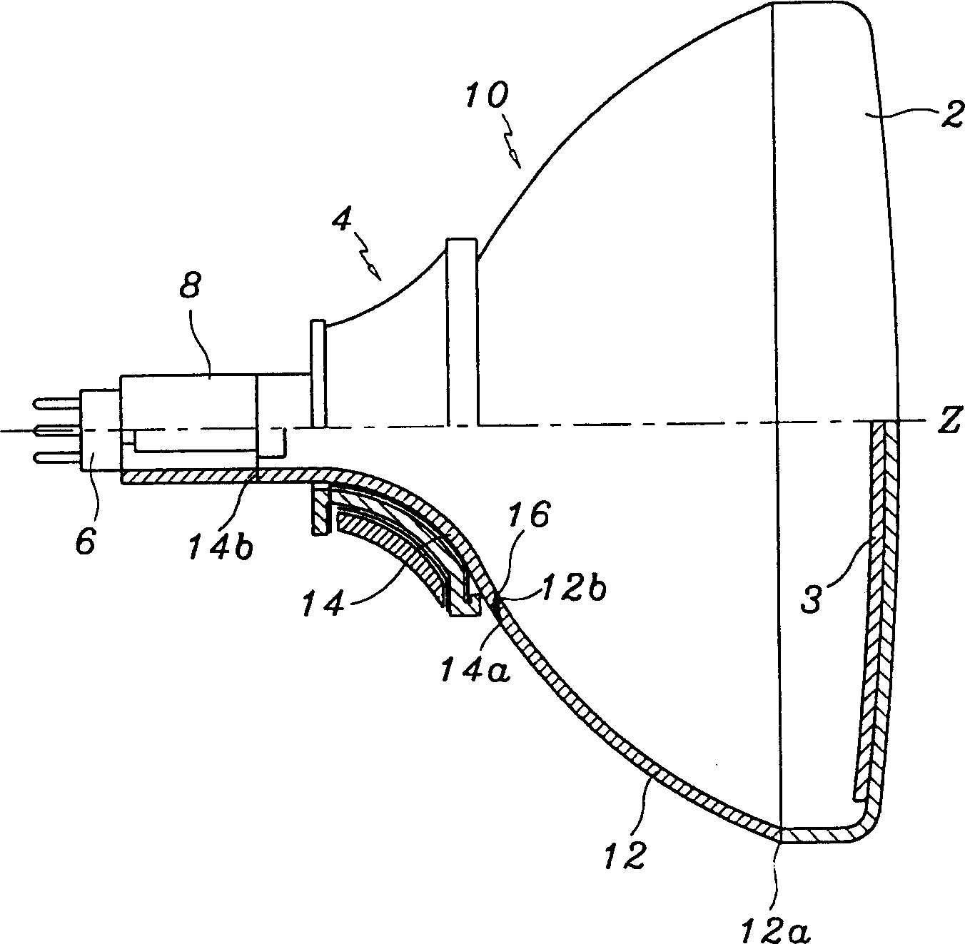
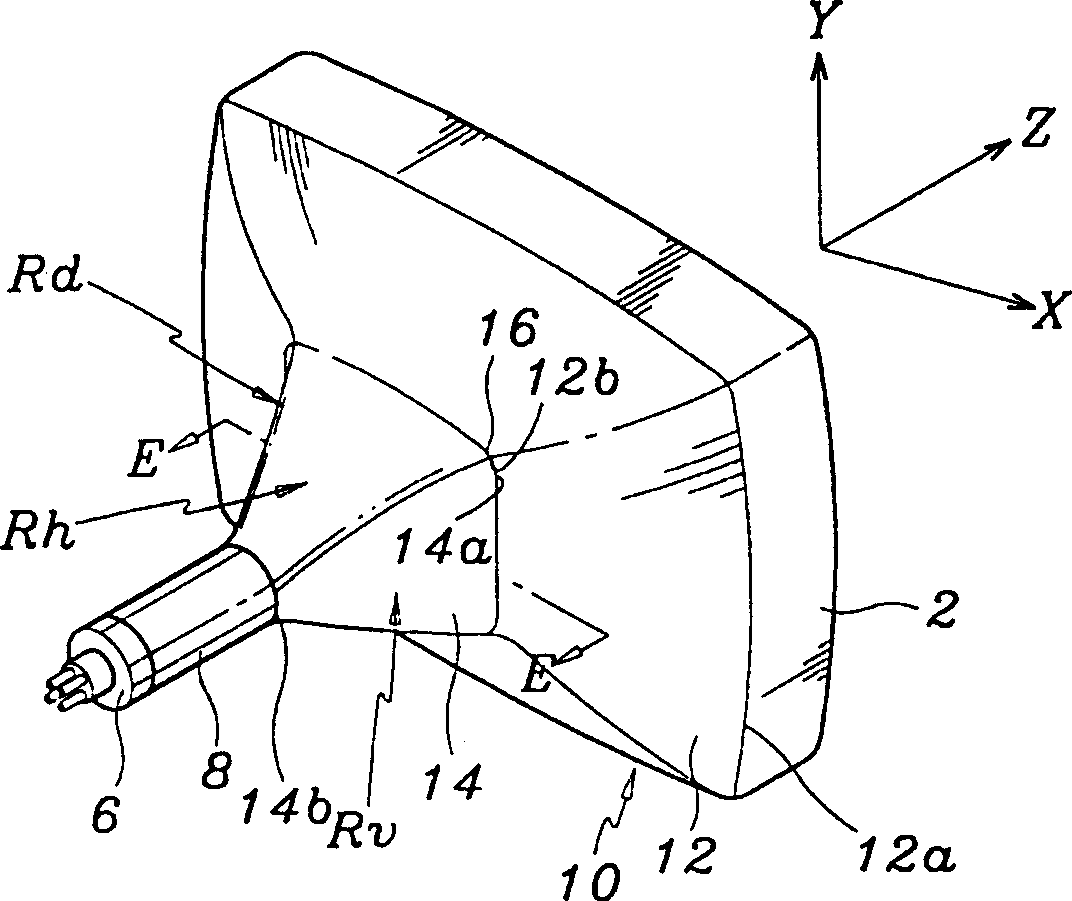
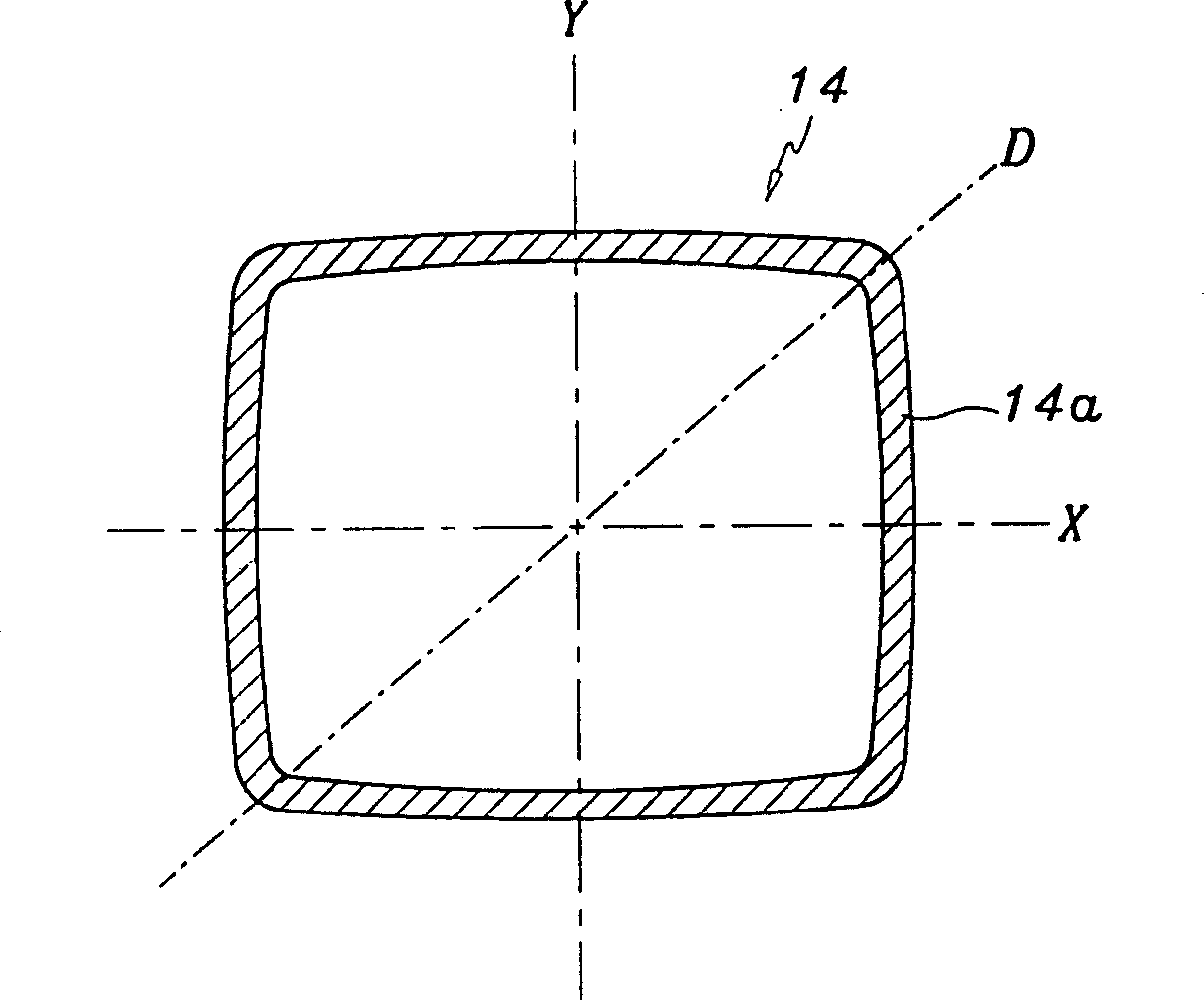
[0023] figure 1 is a partial cross-sectional view of a CRT having a panel 2 according to a preferred embodiment of the present invention, figure 2 yes figure 1 Perspective view of the CRT shown, image 3 is along figure 2 The cross-sectional view of the CRT obtained by the E-E line. The panel 2 has a substantially rectangular effective screen portion having two long sides in the direction of the horizontal axis, two short sides in the vertical direction, and four edges in the direction of the oblique axis. In the figure, Z represents the central axis of the CRT, hereinafter referred to as the "tube axis", X represents the axis of the panel 2 in the horizontal direction, hereinafter referred to as the "horizontal axis", and Y represents the axis in the vertical direction, hereinafter referred to as the "vertical axis". The axis of the panel 2, and D denotes the axis ...


PUM


Abstract

A cathode ray tube includes a panel with an inner phosphor screen and a rear portion. The panel has a substantially rectangular effective screen portion. A funnel is connected to the rear portion of the panel. The funnel sequentially has a body and a cone portion.The small-sized end of the body meets the large-sized end of the cone portion at a point. The meeting point becomes an inflection point of the funnel. The cone portion is provided with a curvature radius Rh in the horizontal axis direction, a curvature radius Rv in the vertical axis direction, and a curvature radius Rd in the diagonal axis direction. A neck is sealed to the small-sized end of the cone portion. An electron gun is fitted within the neck to produce electron beams. A deflection yoke is mounted around the cone portion of the funnel. Rh, Rv and Rd satisfy the following condition: Rh < Rv < Rd.

Description

technical field [0001] The present invention relates to a cathode ray tube (CRT), and more particularly to a CRT capable of effectively improving electron beam deflection efficiency. Background technique [0002] A CRT generally includes: a faceplate with an inner phosphor screen; a funnel with a conical portion; and a neck with an electron gun inside, which are connected in turn. Deflection yokes are mounted around the conical portion of the funnel to form horizontal and vertical magnetic fields there. In this structure, an electron beam emitted from an electron gun is deflected by horizontal and vertical magnetic fields of a deflection yoke, and lands on a phosphor screen. [0003] Recently, CRTs have been used in highly sophisticated electronic equipment such as High Definition Television (HDTV) and OA (Office Automation) equipment. [0004] On the other hand, in these applications, the power consumption of the CRT should be reduced to obtain good energy efficiency, and...

Claims


Application Information

Patent Timeline
IPC IPC(8): H01J29/76H01J29/86
CPCH01J2229/8609H01J29/861H01J29/76
Inventor 李逢雨
Owner SAMSUNG ELECTRONICS DEVICES CO LTD
Why Eureka
Try Eureka