Parking brake unit and electromechanical brake clamp

A parking brake and cylinder technology, applied in the field of rail transit, can solve problems such as low energy storage efficiency, and achieve the effects of high energy storage efficiency, rapid energy release, and compact structure

Active Publication Date: 2021-12-24
CRRC QINGDAO SIFANG ROLLING STOCK RES INST
View PDF7 Cites 1 Cited by
  • Summary
  • Abstract
  • Description
  • Claims
  • Application Information

AI Technical Summary

Problems solved by technology

[0004] The present invention aims at the above-mentioned problems of low energy storage efficiency existing in the existing electromechanical brake caliper, and provides a parking brake unit and an electromechanical brake caliper with a compact structure and high energy storage efficiency, without hydraulic pressure and air pressure, It can provide braking force for parking braking, emergency braking and other working conditions of rail vehicles to ensure the safety of rail vehicles, and has compact axial structure and small size

Method used


Image

  • Parking brake unit and electromechanical brake clamp
  • Parking brake unit and electromechanical brake clamp
  • Parking brake unit and electromechanical brake clamp

Examples


Embodiment 1

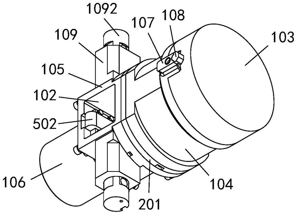
[0079] Embodiment 1: see figure 1 , the present embodiment provides a parking brake unit, comprising:

[0080] The cylinder block assembly is provided with a cavity 101 with a first square hole 102 inside; the cylinder block assembly includes:

[0081] the first cover 103;

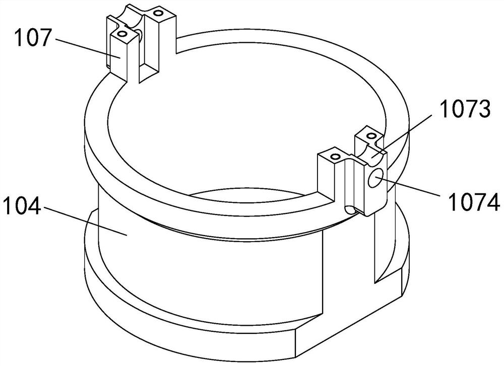
[0082] The first cylinder 104 is connected with the first cover 103, and the end of the first cylinder 104 connected with the first cover 103 is provided with two symmetrical protrusions 107, which are respectively the first protrusion 1071 and the second protrusion 107. Two protrusions 1072, each protrusion 107 is connected to the first cover 103 through a fixing piece 108;

[0083] The second cylinder 105 is connected with the first cylinder 104. Two symmetrical cylinders 109 are arranged on the outside of the second cylinder 105. A mounting hole 1091 is provided in the cylinder 109, and a pin sensor is installed in the mounting hole 1091. ; The first square hole 102 is opened on the side of the secon...

Embodiment 2

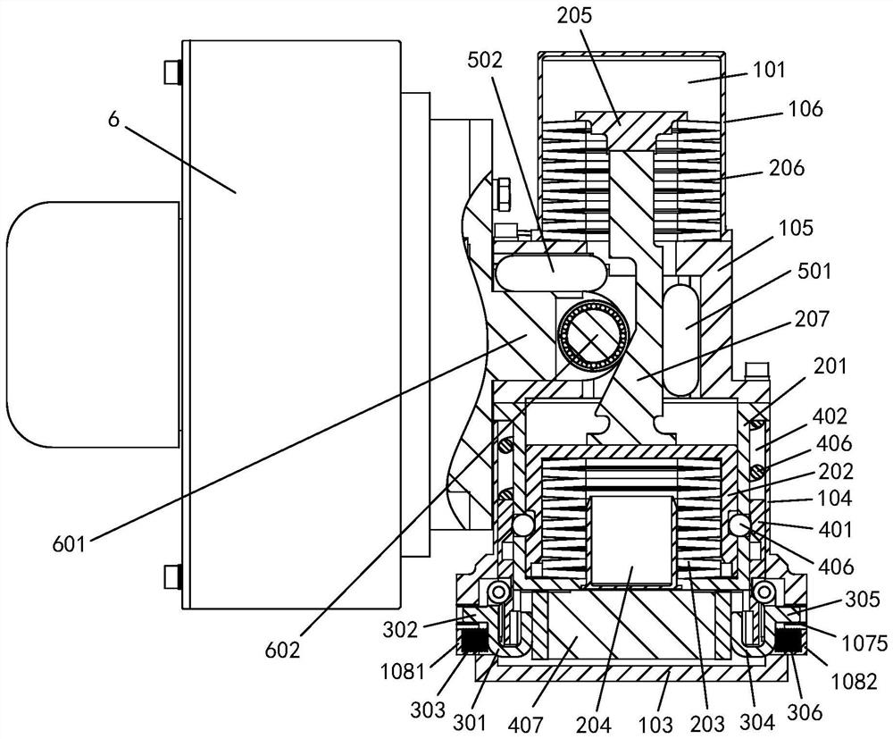
[0130] Example 2: see figure 2 , Figure 15 , this embodiment provides an electromechanical brake caliper, including:

[0131] Pliers bracket 7;

[0132] Two pliers arms are symmetrically installed on the pliers body support 7;

[0133] Brake assembly 8 is installed on the end of the clamp arm;

[0134] Electromechanical brake cylinder, mounted between the two caliper arms, consisting of:

[0135] The spring energy storage unit 9 adopts the parking braking unit described in embodiment 1, and the parking braking unit is hinged with the first pincer arm 10 by a pin sensor;

[0136] The electric drive unit 6 is vertically arranged with the spring energy storage unit 8, and the electric drive unit 6 is provided with a support beam 603, and the electric drive unit 10 is hinged with the second pincer arm 11 by the support beam 603; the output member action part of the electric drive unit 6 601 protrudes into the cavity of the parking brake unit, and the roller assembly 602 pro...


PUM


Abstract

The invention relates to a parking brake unit and an electromechanical brake clamp, and the parking brake unit comprises a cylinder assembly which is internally provided with a cavity with a hole; an energy storage assembly which is located in the cavity and comprises a disc spring cylinder body fixed to the cylinder assembly; a disc spring sleeve sleeved in the disc spring cylinder body; a disc spring assembly I located in the disc spring sleeve; a guide piece positioned in the disc spring assembly I and fixedly arranged at the end part of the disc spring cylinder body; a supporting piece located in the cavity and arranged with the disc spring sleeve in a spaced mode; a disc spring assembly II located in the cavity and arranged between the supporting piece and the cylinder body assembly; a wedge-shaped piece, wherein one end, close to the bearing slope, of the wedge-shaped piece is connected with the disc spring sleeve, and the other end penetrates through the disc spring assembly II to be connected with the supporting piece; a thrust output control unit connected with the disc spring cylinder body; and a locking assembly located between the disc spring cylinder body and the disc spring sleeve. The parking brake unit is compact in structure, high in energy storage efficiency, small in axial size and light in weight, and energy is generated by elastic potential energy of the disc spring set.

Description

technical field [0001] The invention belongs to the technical field of rail transit, and relates to rail vehicle braking technology, in particular to a parking brake unit and an electromechanical brake caliper. Background technique [0002] With the innovation of industrial control technology and the continuous improvement of the overall performance requirements of rail transit, the requirements for the electrification of rail vehicle brakes continue to increase, and intelligence, networking and light weight have become the development trend. Electrified brakes no longer require extensive piping and power sources such as hydraulics or pneumatics. In the electrified brake, a key technology is how to reliably ensure the brake output in the power-off state and the long-term braking force retention of the parking brake. The traditional parking cylinder can no longer meet the requirements. [0003] At present, the parking function of the existing electromechanical brake caliper ...

Claims


Application Information

Patent Timeline
Patent Type & Authority Applications(China)
IPC IPC(8): B60T13/74
CPCB60T13/743
Inventor 杨磊马法运王帅刘帅夏志远冯勇孙国斌
Owner CRRC QINGDAO SIFANG ROLLING STOCK RES INST
Why Eureka
Try Eureka