Hydraulic valve port submerged jet erosion visual experiment system and experiment method

An experimental system, hydraulic valve technology, applied in the direction of testing wear resistance, measuring devices, instruments, etc., can solve the problems of poor uniformity of oil particles and pump wear, etc., to achieve a wide range of use, improve flexibility, and strong practicability Effect

Pending Publication Date: 2021-12-24
LANZHOU UNIVERSITY OF TECHNOLOGY
View PDF0 Cites 0 Cited by
  • Summary
  • Abstract
  • Description
  • Claims
  • Application Information

AI Technical Summary

Problems solved by technology

[0010] The purpose of the present invention is to provide a hydraulic valve port submerged jet erosion visualization experiment system and test method to solve the problems in the above-mentioned prior art that the pump directly inhales the mixed liquid to cause wear to the pump and the uniformity of particles in the oil is poor. question

Method used


Image

  • Hydraulic valve port submerged jet erosion visual experiment system and experiment method
  • Hydraulic valve port submerged jet erosion visual experiment system and experiment method
  • Hydraulic valve port submerged jet erosion visual experiment system and experiment method

Examples


Embodiment 1

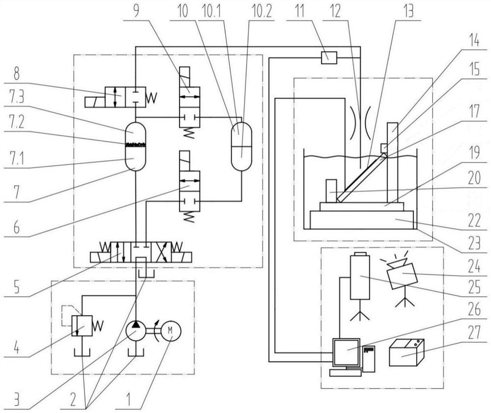
[0063] Such as figure 1 As shown, this embodiment provides a hydraulic valve port submerged jet erosion visualization experiment system, specifically a particle (test particle)-wall surface (the sprayed plate surface of the baffle 17) erosion during the hydraulic valve port submerged jet process The visualization experiment system includes a power unit, a particle-oil mixing unit, a particle-oil submerged jet unit, a measurement unit and a particle recovery unit. in:

[0064] The power unit includes a motor 1, a pump 3, an oil tank 2 and an overflow valve 4, the motor 1 is connected to the pump 3, the inlet of the pump 3 is connected to the oil tank 2, the outlet of the pump 3 is connected in parallel with the overflow valve 4, and the outlet of the overflow valve 4 The outlet is connected back to fuel tank 2. Wherein, the pump 3 is preferably a gear pump, and the oil tank 2 connected to the pump 3 and the oil tank 2 connected to the outlet of the overflow valve 4 may be the...


PUM


Abstract

The invention discloses a hydraulic valve port submerged jet erosion visual experiment system. The system comprises a power unit, a particle-oil liquid mixing unit, a particle-oil liquid submerged jet flow unit and a measuring unit; two groups of interconnected energy accumulators are used for separating the power unit from mixed particle-containing oil liquid, so that a pump is prevented from being abraded due to the fact that the pump directly sucks the mixed liquid, and sufficient homogenization of particles in the oil liquid is well achieved; by means of a manometer on a baffle, the impact force and distribution characteristics of the particles in the particle-containing oil liquid on a wall surface in the jet flow process can be captured, and a particle-wall surface erosion rule in hydraulic valve port submerged jet flow can be comprehensively obtained on the basis of recording of the collision process of the particles and the baffle by a camera. The hydraulic valve port submerged jet erosion experiment method provided by the invention is mainly realized based on the hydraulic valve port submerging jet erosion visual experiment system, and is simple and convenient to operate and wide in application range.

Description

technical field [0001] The invention relates to the technical field of jet erosion research, in particular to a hydraulic valve port submerged jet erosion visualization experiment system and test method. Background technique [0002] Erosion wear refers to a type of wear phenomenon in which the surface of the material is damaged when it is impacted by small and loose flowing particles. Specifically, it can be described as the relative movement between the solid surface and the fluid containing solid particles, resulting in the loss of its surface material. Erosion wear is a common form of wear in modern industrial production, and it is one of the important reasons for the damage and scrapping of machinery and equipment and its parts. The erosion wear in the hydraulic system belongs to the mud type erosion. The oil entrains the particles and impacts the surface of the part material at a certain speed to cause erosion wear, which seriously affects the reliability and service l...

Claims


Application Information

Patent Timeline
Patent Type & Authority Applications(China)
IPC IPC(8): G01N3/56
CPCG01N3/567G01N2203/0005G01N2203/0048
Inventor 刘新强刘飞冀宏李娜娜张建军
Owner LANZHOU UNIVERSITY OF TECHNOLOGY
Why Eureka
Try Eureka