Interface display control method and device, electronic equipment and storage medium

A technology of interface display and control method, which is applied in the direction of program control device, digital output to display device, user interface execution, etc., can solve problems such as poor user experience, inability to know the current status of intelligent cleaning equipment, poor cleaning effect, etc. Achieve the effect of enhancing timeliness and improving user interaction experience

Pending Publication Date: 2021-12-24
WUXI ROIDMI INFORMATION TECH CO LTD
View PDF0 Cites 0 Cited by
  • Summary
  • Abstract
  • Description
  • Claims
  • Application Information

AI Technical Summary

Problems solved by technology

Users often rely on the operation interface when using smart cleaning equipment, but the existing operation interface only provides functional options, and users cannot know the current status of the smart cleaning equipment

Method used


Image

  • Interface display control method and device, electronic equipment and storage medium
  • Interface display control method and device, electronic equipment and storage medium
  • Interface display control method and device, electronic equipment and storage medium

Examples


Embodiment 1

[0051] figure 1 It is a flowchart of an interface display control method provided by Embodiment 1 of the present invention. This embodiment is applicable to the situation of real-time display of the working status of an intelligent electronic device. This method can be executed by an interface display control device. The interface display control The apparatus can be configured on computer equipment, and the computer equipment can be composed of two or more physical entities, or can be composed of one physical entity.

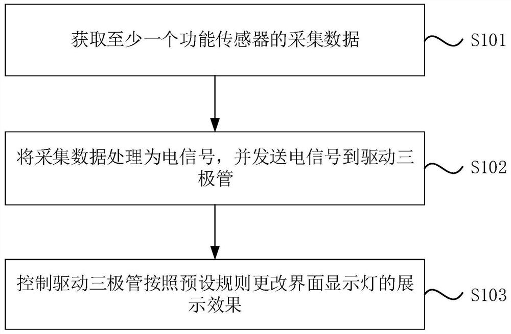
[0052] Such as figure 1 As shown, the interface display control method provided in Embodiment 1 is applied to the control unit, and specifically includes the following steps:

[0053] S101. Acquire collection data of at least one functional sensor.

[0054] Wherein, each functional sensor is arranged in the electronic device.

[0055] In this embodiment, the control unit can be understood as an electronic control element disposed on the electronic device to co...

Embodiment 2

[0069] Figure 4 It is a flowchart of an interface display control method provided by Embodiment 2 of the present invention. The technical solution of the embodiment of the present invention is further optimized on the basis of the above-mentioned optional technical solutions. When the functional sensor is an infrared sensor, the control of the infrared sensor The sending tube sends infrared signals in the cleaning device; the receiving tube of the infrared sensor is controlled to receive the infrared signals; the difference between the sent infrared signals and the received infrared signals is determined as the degree of dirt; the dirt display electrical signal corresponding to the degree of dirt is found , and send the dirty display electrical signal to the driving triode; when the functional sensor is an electromagnetic induction sensor, control the electromagnetic induction sensor to collect the electromagnetic induction intensity of the water purification pipe, wherein the...

Embodiment 3

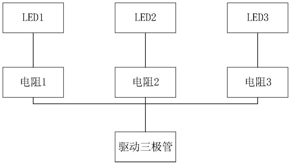
[0096] Figure 7 A schematic structural diagram of an interface display control device provided in Embodiment 3 of the present invention, the interface display control device can be applied to a control unit, and the interface display control device includes: a data acquisition module 31, a signal conversion module 32 and a display control module 33 .

[0097] Wherein, the data acquisition module 31 is used to obtain the collected data of at least one functional sensor, wherein each functional sensor is arranged in an electronic device; the signal conversion module 32 is used to process the collected data into electrical signals, and send the electrical signals to the drive triode ; The display control module 33 is used to control the driving triode to turn on and off the interface display light according to preset rules.

[0098] In the technical solution of this embodiment, when the electronic device is working, data is collected through a plurality of functional sensors ar...


PUM


Abstract

The invention discloses an interface display control method and device, electronic equipment and a storage medium. The method comprises the steps of acquiring collection data of at least one functional sensor, wherein all the functional sensors are arranged on the electronic equipment; processing the collected data into an electric signal, and sending the electric signal to a driving triode; and controlling the driving triode to change the display effect of the interface display lamp according to a preset rule. According to the technical scheme provided by the embodiment of the invention, the working state of the electronic equipment is displayed in real time through the display interface, so that the problem that the working state of the intelligent electronic equipment is difficult to obtain is solved, the timeliness of monitoring the state of the electronic equipment is enhanced, and the user interaction experience is improved.

Description

technical field [0001] The embodiments of the present invention relate to the technical field of automation control, and in particular to an interface display control method, device, electronic equipment and storage medium. Background technique [0002] Smart cleaning equipment has become an indispensable equipment in today's life. Users often rely on the operation interface when using smart cleaning equipment, but the existing operation interface only provides functional options, and users cannot know the current status of the smart cleaning equipment, resulting in poor user experience. For example, the cleaning device of the smart cleaning device is too dirty, but the user cannot know it, resulting in poor cleaning effect after the smart cleaning device finishes cleaning. In order to solve the above problems, there is an urgent need for a cleaning device display interface to meet the real-time display of the status of the smart cleaning device, so as to enhance the user's...

Claims


Application Information

Patent Timeline
IPC IPC(8): G06F3/14G06F9/451
CPCG06F3/1407G06F9/451
Inventor 周建春
Owner WUXI ROIDMI INFORMATION TECH CO LTD
Why Eureka
Try Eureka