[0034] In order to make the objectives, technical solutions and advantages of the present application clearer, the technical solutions of the present application will be clearly and completely described below with reference to the specific embodiments of the present application and the corresponding drawings. Obviously, the described embodiments are only a part of the embodiments of the present application, but not all of the embodiments. Based on the embodiments in the present application, all other embodiments obtained by those of ordinary skill in the art without creative efforts shall fall within the protection scope of the present application.
[0035] The technical solutions provided by the embodiments of the present application will be described in detail below with reference to the accompanying drawings.
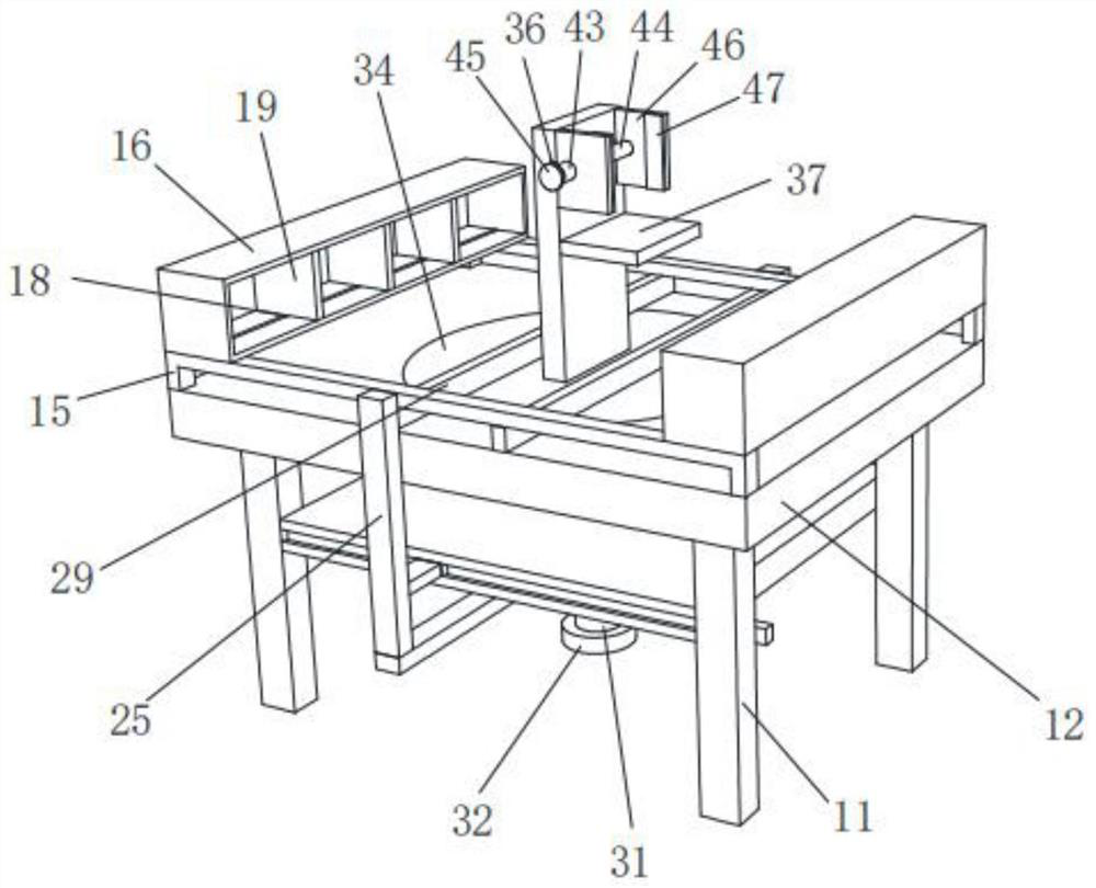
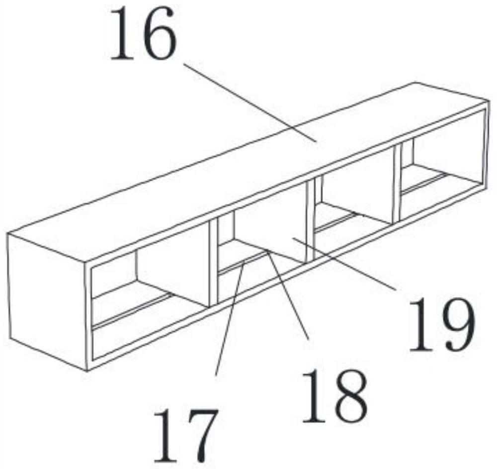
[0036] see figure 1 , figure 2 , image 3 , Figure 4 , Figure 5 , Image 6 , Figure 7 , Figure 8 and Figure 9 , a workbench for medical nursing and teaching, comprising support legs 11, a workbench 12 is fixedly installed at the ends of the four support legs 11, a circular groove 13 is opened at the center of the end of the workbench 12, and the inner wall of the circular groove 13 is provided with The column slot 14 and the end of the worktable 12 are symmetrically fixed with fixing bars 15, the ends of the two fixing bars 15 are fixedly installed with storage boxes 16, and the two inner walls of the two storage boxes 16 are provided with chute 17 on both sides. A sliding block 18 is movably installed inside the groove 17, and a partition 19 is fixedly installed between each group of the sliding block 18;
[0037]A cleaning mechanism is fixedly installed between the four support legs 11;
[0038] A steering mechanism is arranged inside the cleaning mechanism;
[0039] A fixing mechanism is fixedly installed on the side wall of the steering mechanism.
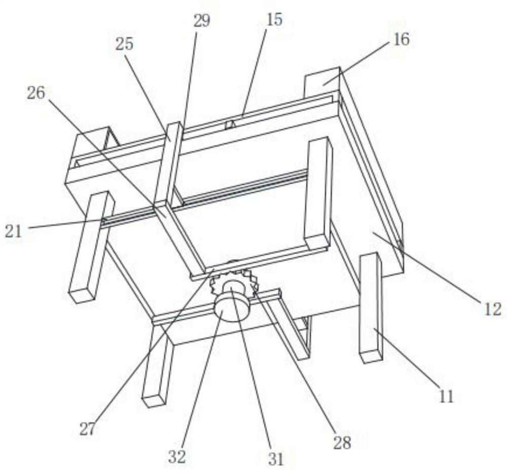
[0040] The cleaning mechanism includes a connecting plate 21, the connecting plate 21 is fixedly installed between the four supporting legs 11, the two side walls of the connecting plate 21 are symmetrically provided with a first dovetail groove 22, and the two first dovetail grooves 22 are movably installed with a first dovetail groove 22. Dovetail blocks 23, the side walls of the two first dovetail blocks 23 are fixedly installed with connecting bars 24, the side walls of the two connecting bars 24 are fixedly installed with first connecting rods 25, and the bottoms of the two first connecting rods 25 are fixedly installed with The second connecting rods 26 , the side walls of the two second connecting rods 26 are fixedly mounted with racks 27 , the gears 28 are engaged between the two racks 27 , and the two first connecting rods 25 are away from one side of the second connecting rod 26 . The cleaning rods 29 are fixedly installed on the sides, the side walls of the two fixing bars 15 are both provided with strip-shaped grooves, and the two cleaning rods 29 are movably arranged in the strip-shaped grooves.
[0041] The steering mechanism includes a threaded column 31. The sidewall of the threaded column 31 is evenly and equally spaced with teeth fixedly installed. The inner wall of the gear 28 is provided with a tooth slot, and the teeth are movably arranged in the tooth slot. The end of the threaded column 31 is fixedly installed with a rotating cap 32. , the side of the threaded post 31 away from the threaded post 31 is provided with a first threaded sleeve 33, the end of the first threaded sleeve 33 is fixedly installed with a lifting plate 34, and the first threaded sleeve 33 and the lifting plate 34 are respectively movably installed in the column groove 14 and the circular groove 13, the first threaded sleeve 33 and the lifting plate 34 are adapted to the column groove 14 and the circular groove 13 respectively, and the side of the lifting plate 34 away from the first threaded sleeve 33 is fixedly installed with a fixing rod 35, two The cleaning rods 29 are arranged in parallel on the surface of the workbench 12, the fixing rod 35 is arranged between the two cleaning rods 29, the side wall of the fixing rod 35 is provided with a second dovetail groove 36, and the side wall of the second side plate 46 is fixedly installed with a second dovetail. Block 48, the second dovetail block 48 is movably installed inside the second dovetail groove 36, and the bottom plate 37 is fixedly installed at the center of the side wall of the fixing rod 35.
[0042] The fixing mechanism includes a first side plate 41, the first side plate 41 is fixedly connected with the fixing rod 35, a first clamp plate 42 is fixedly installed on the side wall of the first side plate 41, and a second screw sleeve 43 is threadedly installed inside the first side plate 41 , a central column 44 is fixedly installed inside the second nut 43, a nut 45 is fixedly installed at the end of the central column 44, and a second side plate 46 is movably sleeved on the side of the central column 44 away from the nut 45. The second side plate A second splint 47 is fixedly installed on the side wall of the 46, the end of the center column 44 penetrates the second side plate 46 and then a fixed plate 49 is fixedly installed. Then, the nut 45 can be rotated, and the second nut 43 fixed with it is driven to rotate on the first side plate 41 under the rotation of the nut 45. At this time, the second nut 43 drives the central column 44 fixed with it. The fixed plate 49 and the fixed plate 49 rotate accordingly. At this time, the central column 44 drives the fixed plate 49 fixed with it to move backward, and the fixed plate 49 squeezes the second side plate 46 to move backward. At this time, the second side plate 46 drives the The fixed second dovetail block 48 moves backward in the second dovetail groove 36, and the second side plate 46 drives the second clamp plate 47 to move toward the first clamp plate 42 to clamp the teaching aid, so that the device can hold the teaching aid when in use. Effective clamping and fixing can effectively ensure the stability of the teaching aid during the teaching process, and then the rotating cap 32 can be rotated clockwise, and the threaded post 31 fixed to it can be driven to rotate clockwise under the clockwise rotation of the rotating cap 32. At this time, the clockwise rotation of the threaded column 31 drives the fixed gear 28 to rotate clockwise, and the gear 28 drives the two racks 27 meshed with it to move relative to each other. At this time, the rack 27 drives it. The cleaning rod 29 fixedly connected by the second connecting rod 26 and the first connecting rod 25 moves relatively on the surface of the workbench 12 . At this time, the two cleaning rods 29 clean the dust on the surface of the workbench 12 , so that the equipment is in use. The surface of the worktable 12 can be effectively cleaned, and the cleaning effect is better; at the same time, when the threaded column 31 rotates inside the first threaded sleeve 33, it continues to move upward, and when the threaded column 31 rotates to the top of the first threaded sleeve 33, At this time, under the action of the thread, the first screw sleeve 33 is driven to move upward, the first screw sleeve 33 drives the lifting plate 34 to move upward, and the lifting plate 34 drives the fixing rod 35 fixed to it to move upward, so that the teaching aid can be moved upward. Lift and flip, and adjust the height and angle of the teaching aids, making it more convenient and labor-saving to adjust the angle and height of the teaching aids when the device is in use.
[0043] When in use, the first step is to place the teaching aid on the bottom plate 37, then the nut 45 can be rotated, and the rotation of the nut 45 drives the second screw sleeve 43 fixed to it to rotate on the first side plate 41 At this time, the second screw sleeve 43 drives the central column 44 and the fixed plate 49 fixed with it to rotate, and the central column 44 drives the fixed plate 49 fixed to it to move backward, and the fixed plate 49 squeezes the second The side plate 46 moves backward, at this time the second side plate 46 drives the second dovetail block 48 fixed to it to move backward in the second dovetail groove 36 , and the second side plate 46 drives the second clamp plate 47 to the first clamp plate 42 The teaching aids are clamped by moving, so that the device can effectively clamp and fix the teaching aids when in use, and effectively ensure the stability of the teaching aids in the teaching process.
[0044] In the second step, the rotating cap 32 can be rotated clockwise, and the threaded post 31 fixed to it is driven to rotate clockwise when the rotating cap 32 rotates clockwise. The gear 28 rotates clockwise, and the gear 28 drives the two racks 27 meshed with it to move relative to each other. The cleaning rod 29 moves relatively on the surface of the worktable 12, and at this time, the two cleaning rods 29 clean the dust on the surface of the worktable 12, so that the equipment can effectively clean the surface of the worktable 12 when in use, and the cleaning effect is better;
[0045] In the third step, at the same time, when the threaded post 31 rotates inside the first threaded sleeve 33, it continues to move upward, and when the threaded post 31 rotates to the top of the first threaded sleeve 33, the first threaded rod is driven by the action of the thread at this time. The sleeve 33 moves upward along with it, the first screw sleeve 33 drives the lifting plate 34 to move upward along with it, and the lifting plate 34 drives the fixed rod 35 fixed to it to move upward to lift and turn the teaching aids, and adjust the height and angle of the teaching aids. Adjustment makes it more convenient and labor-saving to adjust the angle and height of the teaching aid when the device is in use.
[0046] As will be appreciated by one skilled in the art, embodiments of the present invention may be provided as a method, system, or computer program product. Accordingly, the present invention may take the form of an entirely hardware embodiment, an entirely software embodiment, or an embodiment combining software and hardware aspects. Furthermore, the present invention may take the form of a computer program product embodied on one or more computer-usable storage media (including, but not limited to, disk storage, CD-ROM, optical storage, etc.) having computer-usable program code embodied therein.
[0047] It should also be noted that the terms "comprising", "comprising" or any other variation thereof are intended to encompass a non-exclusive inclusion such that a process, method, article or device comprising a series of elements includes not only those elements, but also Other elements not expressly listed, or which are inherent to such a process, method, article of manufacture, or apparatus are also included. Without further limitation, an element qualified by the phrase "comprising a..." does not preclude the presence of additional identical elements in the process, method, article of manufacture, or device that includes the element.
[0048] The above descriptions are merely examples of the present application, and are not intended to limit the present application. Various modifications and variations of this application are possible for those skilled in the art. Any modification, equivalent replacement, improvement, etc. made within the spirit and principle of this application shall be included within the scope of the claims of this application.