Multi-degree-of-freedom suction arm support and dredging vehicle

A degree of freedom and boom technology, applied in waterway systems, cleaning sewer pipes, water supply devices, etc., can solve the problems of effectively controlling multiple angles of the suction pipeline, low work efficiency, and high labor costs, and achieves improved automation. The effect of reducing labor costs and improving work efficiency

Pending Publication Date: 2021-12-28
JIANGSU XCMG CONSTR MASCH RES INST LTD
View PDF8 Cites 0 Cited by
  • Summary
  • Abstract
  • Description
  • Claims
  • Application Information

AI Technical Summary

Problems solved by technology

During the operation, the simple fixed boom has single action and function, low work efficiency, high labor cost, and cannot meet the needs of most working conditions; although the rotating telescopic boom has the functions of lifting and turning, but because the suction pipeline is The suspension of the hose is not fixed, the hose will swing, and multiple people are still required to coordinate the operation, and the weight of the suction pipe is heavy, which increases the work intensity of the suction. In certain urban working conditions with limited space , the rotating telescopic boom cannot accurately and effectively control the multi-angle and multi-directional suction operations of the suction pipeline, which increases the difficulty of work, labor costs, and increases the work intensity of suction, and the work efficiency is low
[0004] In the process of completing the operation and transportation, since the position of the tank body inlet is not sealed, various sewage, odorous gases and other media in the tank body will flow out or emit through the suction hose of the suction arm during transportation. , affecting the cleanliness of municipal roads, toxic and harmful gases may even cause secondary pollution

Method used


Image

  • Multi-degree-of-freedom suction arm support and dredging vehicle
  • Multi-degree-of-freedom suction arm support and dredging vehicle
  • Multi-degree-of-freedom suction arm support and dredging vehicle

Examples


Embodiment 1

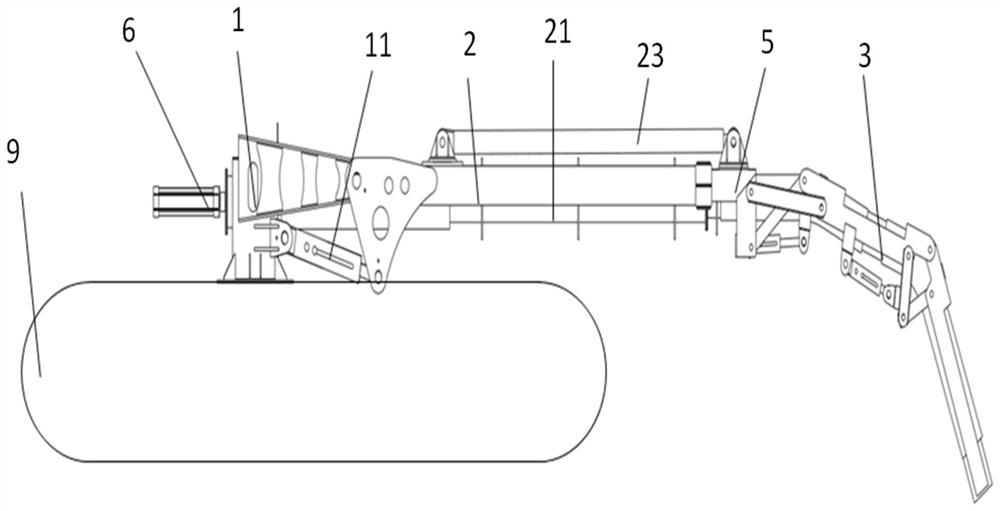
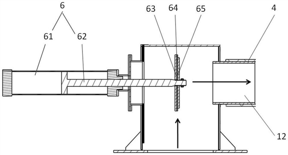
[0041] The invention provides a multi-degree-of-freedom suction boom, please refer to figure 1 , including a rotary mechanism 1, a lifting mechanism 2, a luffing mechanism 3, a suction hose 4 and a sliding mechanism 5, the rotary mechanism 1 is arranged at the material inlet of the tank body 9, the lifting mechanism 2 and the rotary Mechanism 1 is in transmission connection, the sliding mechanism 5 is in transmission connection with the lifting mechanism 2, the luffing mechanism 3 is in transmission connection with the sliding mechanism 2, and the discharge port 12 of the slewing mechanism 1 is connected with an overflow-proof sealing mechanism 6 , the slewing mechanism 1 is connected with the lifting mechanism 2 through the suction hose 4, the lifting mechanism 2 is connected with the sliding mechanism 5 through the suction inner and outer tubes, and the sliding mechanism 5 and the luffing mechanism 3 are connected through the suction Suction hose 4 connections.

[0042] Speci...

Embodiment approach

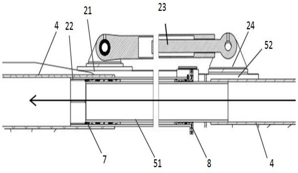
[0050] The first sealing mechanism 7 is arranged between the suction outer pipe 22 and the suction inner pipe 51, and the first sealing mechanism 7 is arranged at one end close to the rotary mechanism 1 to make the suction outer pipe 22 and the suction The inner tube 51 is gap-connected. As a preferred embodiment, the first sealing mechanism 7 includes a first guiding dirt-receiving ring 71, a piston seal 73, a V-shaped combined seal 74 and a slider 72, please refer to Figure 5 . Specifically, the first guide dirt-receiving ring 71, piston seal 73, V-shaped combined seal 74 plug and slider 72 are sequentially sleeved on the suction inner tube 51, and the slider 72 is located near the rotary mechanism 1. One end, in this embodiment, the slider 72 is a nylon slider, and the nylon slider acts as a guide. Institution 2 is connected.

[0051] The second sealing mechanism 8 is arranged between the suction outer tube 22 and the suction inner tube 51 to make the gap connection bet...

Embodiment 2

[0056] The present invention also provides a dredging vehicle, which adopts the multi-degree-of-freedom suction boom described in the first embodiment.

[0057] In this embodiment, the multi-degree-of-freedom suction arm is erected on the frame of the dredging vehicle. When the suction operation is required, the rotary mechanism 1 can rotate to different angles relative to the tank body 9, so that the third section The rear end of the arm 313 is used to extend to the sewer for suction work, and the media such as sludge, accumulated sand and stone, and consolidated waste are sucked to the lifting mechanism 2, the sliding mechanism 5, the turning mechanism 1 and the tank in sequence. 9 inside the body.

[0058] The lifting mechanism 2, the sliding mechanism 5, and the multi-degree-of-freedom luffing mechanism 3 are sealed and connected, and through the first luffing cylinder 32, the second luffing cylinder 11, and the telescopic oil cylinder 23, multiple degrees of freedom and m...


PUM


Abstract

The invention discloses a multi-degree-of-freedom suction arm support and a dredging vehicle. The multi-degree-of-freedom suction arm support comprises a swing mechanism, a lifting mechanism, a slip mechanism, a luffing mechanism and a suction hose, the lifting mechanism comprises lifting arm support and a suction outer pipe, slip mechanism comprises a slip rod and a suction inner pipe, the slip mechanism is in transmission connection with the luffing mechanism through the slip rod, the outer suction pipe sleeves the inner suction pipe, a discharge port of the swing mechanism communicates with an anti-overflow sealing mechanism, and the swing mechanism, the lifting mechanism, the slip mechanism and the luffing mechanism are in pipeline connection through the suction hose. When the dredging vehicle performs suction operation, multi-degree-of-freedom, multi-angle and multi-direction suction can be achieved, meanwhile, a suction pipeline is accurately and effectively controlled so as to perform suction, transfer and other work, and in the transportation process, the anti-overflow sealing mechanism can be used for sealing the feeding port of a tank body, so that secondary pollution caused by sewage and peculiar smell gas overflowing through the suction hose is prevented.

Description

technical field [0001] The invention relates to a multi-degree-of-freedom suction boom and a dredging vehicle, belonging to the technical field of municipal environmental sanitation machinery. Background technique [0002] With the development of cities and towns and the expansion of roads in our country, the demand for dredging and maintenance of urban underground pipe networks is increasing, so the demand for mobile sewer dredging and cleaning vehicles is increasing. The sewer dredging and cleaning vehicle uses high-pressure water jets to directly impact the sludge, accumulated sand, and consolidated waste in the urban underground pipe network, or crushes tree roots, cement, and pipe wall attachments through the front-end rotating nozzle, and then reuses them. The principle of vacuum pneumatic conveying is a kind of equipment that carries out suction operation and conveys materials to the tank for transfer. [0003] At present, the suction booms of sewer dredging and clea...

Claims


Application Information

Patent Timeline
Patent Type & Authority Applications(China)
IPC IPC(8): E03F9/00E03F7/10
CPCE03F9/00E03F7/106
Inventor 吴野韩松峰孙国保景藜王静
Owner JIANGSU XCMG CONSTR MASCH RES INST LTD
Why Eureka
Try Eureka