Peripheral pump capable of preventing impurities from caking
A vortex pump, agglomeration technology, applied in the field of vortex pumps
- Summary
- Abstract
- Description
- Claims
- Application Information
AI Technical Summary
Problems solved by technology
Method used
Image

Examples
specific Embodiment 1
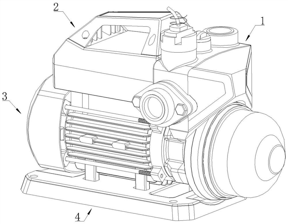
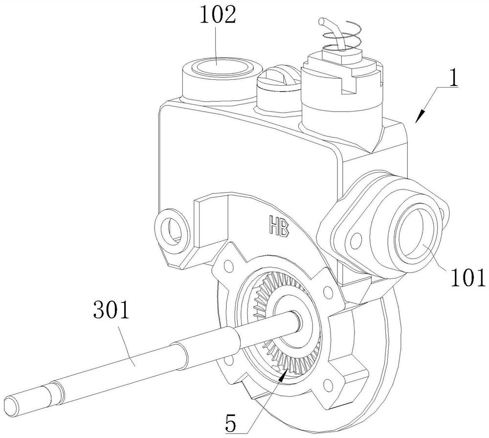
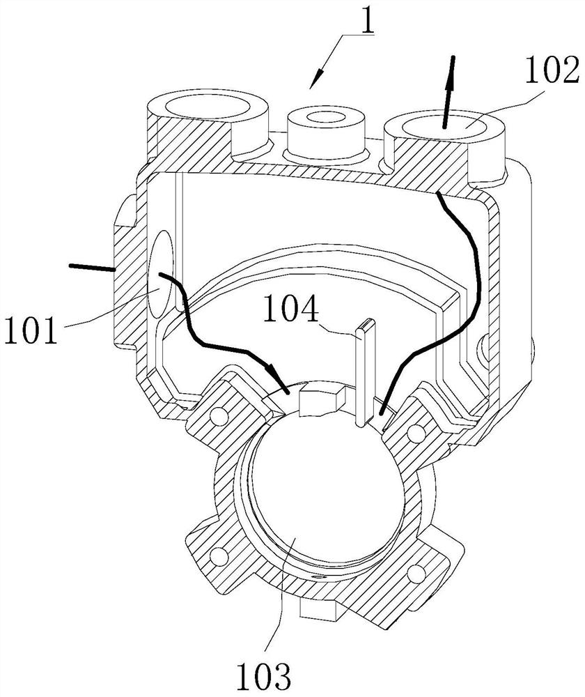
[0046] Specific embodiment one: please refer to Figure 1-5 A vortex pump for preventing impurity agglomeration comprises a pressure tank 1 , a portable wire box 2 , an induction motor 3 and a base 4 . A water inlet 101 and a water outlet 102 are opened on the inner upper side of the pressure tank 1 . Water is passed into the pressure tank 1 through the water inlet 101 , and the water in the pressure tank 1 is discharged through the water outlet 102 .
[0047] An impeller chamber 103 is opened on the lower side inside the pressure tank 1 , and the impeller assembly 5 is arranged in the impeller chamber 103 .
[0048] The impeller assembly 5 is fixedly connected with the rotor 301 of the induction motor 3 , and the impeller assembly 5 is coaxial with the rotor 301 .
[0049] Both sides of the upper end of the impeller chamber 103 are respectively provided with an inlet and an outlet, the inlet is connected to the water inlet 101 , and the outlet is connected to the water outl...
specific Embodiment 2
[0063] Specific embodiment two: on the basis of specific embodiment one, please refer to Figure 6 A vortex pump for preventing impurity agglomeration, the vane 501-1 of the left wheel 501 is provided with an open guide groove 501-2 on the side close to the grinding plate 502. The guide slot 501-2 is opened along the length direction of the vane 501-1, and the guide slot 501-2 extends through the outer peripheral end of the vane 501-1. After the solid impurities are crushed into small particle impurities, due to the centrifugal effect caused by the rotation of the impeller assembly 5, the small particle impurities can be thrown out along the guide groove 501-2.
[0064] A collecting box 105 is fixedly arranged at the lower end of the impeller cavity 103 , and the collecting box 105 communicates with the impeller cavity 103 .
[0065] After the impeller assembly 5 stops rotating, small particles of impurities are thrown out by the centrifugal force, and are collected in the lo...
specific Embodiment 3
[0066] Specific embodiment three: on the basis of specific embodiment one or two, please refer to Figure 7 A vortex pump that prevents impurities from agglomerating, a filter unit 6 is provided in the water outlet chamber, and the filter unit 6 filters solid impurities, effectively avoiding the problem of low purity of the discharged water.
[0067] The filter unit 6 includes a filter plate 601 . The filter plate 601 is located in the water outlet chamber. The surface of the filter plate 601 is provided with a plurality of through filter ports. The solid impurities can be blocked on the lower end surface of the filter plate 601 , and the water body can flow through the filter plate 601 . The filter plate 601 is fixedly connected between the partition plate 104 and the inner wall of the pressure tank 1 . The height of the filter plate 601 from the end close to the separator 104 gradually decreases toward the end close to the inner wall of the pressure tank 1 . The side end...
PUM
 Abstract
Description
Claims
Application Information
 - R&D Engineer
- R&D Manager
- IP Professional
- Industry Leading Data Capabilities
- Powerful AI technology
- Patent DNA Extraction
Browse by: Latest US Patents, China's latest patents, Technical Efficacy Thesaurus, Application Domain, Technology Topic.
© 2024 PatSnap. All rights reserved.Legal|Privacy policy|Modern Slavery Act Transparency Statement|Sitemap